Planetary gear motor thermal capacity determines whether catalog torque is usable continuously in your machine. Check motor losses, gearbox losses, ambient temperature, and flange heat dissipation together. An S3 intermittent rating cannot be substituted for an S1 continuous rating without evaluating the complete load cycle and the supplier's test conditions.
For an OEM buyer, the useful question is: can this exact motor, gear ratio, lubricant, and mounting arrangement deliver the required torque and speed without exceeding any component temperature limit? A catalog nominal torque of 30 Nm against a required 25 Nm leaves 20% mechanical margin, but does not establish a thermal margin inside a sealed enclosure.
To turn this guide into a sourcing brief, use the planetary gear motor RFQ template and attach the actual motion profile and mounting drawing. Ask the supplier to state the temperature limit, measurement location, and mounting condition behind every continuous rating.
Publication and review date: November 9, 2026. Scope: Global engineering and procurement guidance for low-voltage DC, BLDC, and AC servo planetary gear motor assemblies, approximately 0.05–5 kW. The worked values are hypothetical engineering assumptions, not measured product performance or a customer case study. This article supports preliminary selection; hazardous locations, medical equipment, road vehicles, and other regulated applications need their own applicable standards and validation.
1. The Dual-Source Thermal Mechanism in Planetary Gear Motors
A planetary gear motor has two coupled heat sources: the electric motor and the reduction gearbox. Heat generated in either part can raise the temperature of the other. A motor winding limit therefore cannot establish the permissible gearbox housing temperature, and a cool exterior cannot prove that winding hot spots are safe.
Motor-side power losses
For balanced three-phase windings, copper loss can be estimated using the RMS current in each winding and the resistance of that winding:
P_cu = 3 × I_phase,RMS² × R_phase,hot
R_hot ≈ R_20 × [1 + 0.00393 × (T_winding - 20°C)]
The resistance approximation makes copper resistance at 120°C about 39% higher than at 20°C. Use consistent phase quantities: a controller's DC-bus current is not automatically the winding RMS current, and a measured line-to-line resistance needs interpretation for the motor's connection. A brushed DC motor requires the corresponding armature-loss calculation.
Speed-dependent iron losses, mechanical losses, and any integrated electronics add heat. The maxon explanation of BLDC continuous operation limits connects the operating envelope to winding temperature, heat dissipation, copper losses, and speed-dependent iron losses. Its example winding limit belongs to the motors discussed there; obtain the limit for the motor being purchased.
Gearbox-side power losses
For positive-power motoring at a known operating point, mechanical gearbox efficiency gives a useful energy balance:
P_out = torque_out × speed_out,rpm / 9.549
P_in,gear = P_out / efficiency_gear
P_loss,gear = P_in,gear - P_out
P_loss,total = P_loss,motor + P_loss,gear
Mesh friction, bearings, lubricant movement, and seals all contribute. Their shares vary with speed, load, lubricant viscosity, fill quantity, and construction. A single efficiency percentage at rated load does not describe a gearbox at low load, cold startup, or during regenerative braking.
ISO/TR 14179-1:2001 describes an analytical heat-balance method for mineral-oil-lubricated gear drives. Its reference conditions include 25°C maximum ambient and 95°C maximum oil sump temperature. That is useful context for separating thermal from mechanical capacity; it does not establish a 95°C housing limit or validate a compact grease-filled gear motor.
As an illustrative energy balance, suppose the motor delivers 400 W of shaft power into a gearbox with 90% efficiency. Gearbox output is 360 W and gearbox heat is 40 W. If motor efficiency is 85%, electrical input is 470.6 W and motor heat is 70.6 W. Combined heat is therefore 110.6 W. The distinction between electrical input, motor shaft power, and final gearbox output prevents double counting. No time to overheating follows from these watts alone: thermal resistance, heat capacity, initial temperature, and protection behavior are also required.
2. Duty Cycles Demystified: S1, S2, S3, and S5
The IEC 60034-1:2022 official preview identifies the rating and performance standard cited here. The following duty descriptions are a practical summary, not a conformity assessment. Agree the applicable edition and full duty designation with the supplier; a motor duty designation alone does not rate the gearbox.
S1: Continuous running duty
S1 means operation at constant load long enough to reach thermal equilibrium. Confirm the rating's ambient temperature, input speed, mounting interface, and cooling method. Different manufacturers use different reference fixtures; there is no universal aluminum plate dimension behind all catalog ratings.
A warmer enclosure reduces the available temperature rise. It does not imply a universal 15%, 25%, or 30% torque reduction. Obtain a model-specific derating curve, or calculate a preliminary limit from a supported loss model and validate it on the installed assembly.
S2: Short-time duty
S2 means constant-load operation for a specified duration, followed by a de-energized rest long enough to return near the cooling-medium temperature. An S2 15-minute rating cannot be repeatedly used every 20 minutes unless the actual cooling behavior supports that schedule. State the initial temperature and restart conditions in the RFQ.
S3: Intermittent periodic duty
S3 comprises repeating constant-load operation and de-energized rest, with starting losses insignificant to the temperature rise. Report both the cyclic duration factor and the complete cycle time:
CDF = t_on / (t_on + t_rest) × 100%A 50% duty cycle could mean five seconds on and five seconds off, or five minutes on and five minutes off. These profiles can produce different winding temperature peaks. Holding current during dwell also produces heat and must not be described as de-energized rest. Intermittency may permit higher on-period motor torque, but it never grants permission to exceed gearbox peak torque, speed, bearing, or fatigue limits.
S5: Intermittent periodic duty with electric braking
S5 includes starting, constant-load operation, electric braking, and rest. Frequent acceleration and braking require their losses to be counted explicitly. Regeneration can return mechanical energy to the DC bus or supply, but motor copper loss and gearbox friction still exist; an external braking resistor does not remove those internal losses. Specify the actual drive and energy-management arrangement.
RMS equivalent torque: useful with boundaries
For a repeating profile, calculate the torque root mean square:
T_RMS = sqrt[(T1² × t1 + T2² × t2 + ... + Tn² × tn) / total_cycle_time]Motor-side RMS torque is a copper-loss screening tool when torque is approximately proportional to current and resistance is treated consistently. Output-side RMS torque can assist comparison only when ratio and efficiency assumptions are explicit. It does not capture speed-dependent iron losses, gearbox no-load losses, unequal cooling, or short winding-temperature peaks. Evaluate mechanical fatigue using the gearbox manufacturer's load-spectrum method separately.
Require both an acceptable thermal result and an acceptable mechanical result. Check the maximum torque against the supplier's permitted peak value and its duration and repetition limit. There is no universal peak multiplier such as 1.8 times nominal torque.
3. The Thermal Resistance Network and Flange Heat Dissipation
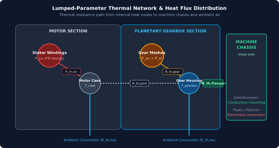
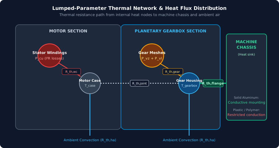
Figure 1: Conceptual thermal network, not measured test data. Motor and gearbox have separate internal temperature drops. Surface cooling and conduction into the machine chassis provide parallel escape paths; the chassis must ultimately reject the conducted heat to its surroundings.
A simplified steady-state housing estimate is:
T_housing ≈ T_ambient + P_loss,total × R_housing-to-ambient,effectiveThermal resistance is expressed in K/W; a temperature difference of 1 K equals a difference of 1°C. Treat the effective resistance as an installation property rather than a universal attribute of the motor diameter.
Winding-to-case resistance
The winding temperature exceeds the case temperature by an internal temperature drop. Insulation, impregnation, winding geometry, and stator fit affect that drop. Use the supplier's winding-to-case thermal resistance and its stated loss definition. In a detailed network, winding copper loss and iron loss enter at different nodes; applying every motor loss at the winding is only a rough lumped approximation.
Housing-to-air cooling
Surface area, orientation, airflow, radiation, and local air temperature affect cooling. A motor inside a sealed robot does not see the same environment as a motor in open laboratory air. Measure the air temperature close to the installed drive and include heat from nearby batteries, controllers, or process equipment. Air movement inside an enclosure can redistribute heat without providing an adequate path out of the enclosure.
Housing-to-chassis conduction
A simple conduction model is:
R_conduction = thickness / (conductivity × contact_area) + R_contact
1 / R_effective ≈ 1 / R_surface-path + 1 / R_complete-chassis-path
The chassis path includes flange contact, heat spreading through the bracket, and final heat rejection from the chassis. Do not model the mounting flange as an infinite heat sink. Coatings, gaps, surface flatness, interface material, bolt preload, and contact area can matter as much as the nominal bracket material. A thick thermal pad may improve contact while adding its own resistance.
The practical procurement question is whether the supplier's thermal test fixture represents the production machine. Ask for a drawing or photograph of the fixture, sensor positions, ambient conditions, speed, load, and stabilization criterion. Neither an aluminum mount nor a steel mount alone establishes a percentage of heat carried through the flange.
A single-node transient model can help explain why cycle time matters:
T(t) = T_ambient + P_loss × R +
       [T_start - T_ambient - P_loss × R] × exp[-t / (R × C)]
Here C is effective thermal capacitance in J/K and loss is assumed constant over the interval. Carry the ending temperature into the next interval. A motor and gearbox usually need multiple nodes to resolve fast winding heating and slower housing heating. Without capacitance data or a measured temperature trace, a steady-state estimate cannot predict cycle peak temperature or an overload timeout.
4. What Temperature Limits Actually Protect
Thermal overload can shorten lubricant life, reduce film thickness, damage seals, and threaten insulation or rotor magnets. These mechanisms have different limits and do not follow one guaranteed sequence. Record the limit and sensor location for each affected component.
Lubricant life and film formation
Grease selection includes base oil, thickener, viscosity, additives, fill quantity, and material compatibility. Higher temperature can accelerate oxidation and alter oil separation, but a claimed service life needs the lubricant manufacturer's data and the gearbox supplier's duty conditions.
A common screening illustration assumes life halves for every 10°C rise:
L(T) = L_reference × 2^[-(T - T_reference) / 10°C]Under that assumed rule, 20,000 hours at 70°C would become 5,000 hours at 90°C and 1,250 hours at 110°C. Those numbers are arithmetic examples, not service intervals for the products in this article. Actual grease behavior can differ substantially. A sealed lifetime-lubricated gearbox may require factory service or replacement rather than field relubrication.
Viscosity also changes with temperature. Obtain the specific lubricant's viscosity-temperature curve instead of treating an ISO viscosity grade as a complete high-temperature specification. Tooth surface finish, contact load, sliding, and lubricant properties determine film formation. Housing temperature alone cannot establish scuffing resistance.
Seals, insulation, and rotor magnets
NBR, FKM, and PTFE describe material families, not guaranteed assembly temperature ratings. Continuous temperature capability depends on the compound, lubricant, shaft speed, pressure, and seal design. A material substitution needs supplier approval and compatibility checking; specifying FKM alone does not make a gearbox suitable for hotter service.
An insulation class is not a permissible gearbox case temperature or an automatic thermostat setpoint. Ask for the motor's approved winding hot-spot limit and protection thresholds. Permanent-magnet capability likewise depends on magnet grade, geometry, and the magnetic working point. Higher-temperature insulation cannot protect an unsuitable magnet, encoder, bearing grease, cable, or adhesive. Use the lowest relevant approved limit with an agreed allowance for measurement uncertainty and hot spots.
5. Engineering Sizing Matrix: Duty Profiles and Required Evidence
Use this matrix to decide what evidence a quotation needs. It intentionally avoids universal torque factors and predicted grease lives: neither can be determined from an application name and ambient temperature alone.
| Installation scenario | Duty information to supply | Thermal concern | Evidence required before selection |
|---|---|---|---|
| Open conveyor on an aluminum frame | S1 torque and input speed | Fixture and production-frame cooling may differ | Continuous temperature trace with the specified flange contact and ambient |
| Enclosed AGV on a coated steel bracket | Complete travel, acceleration, braking, and dwell sequence | Restricted airflow and contact resistance | Winding and gearbox temperature traces inside a representative closed chassis |
| Wheel hub with polymer isolation | Cycle time, dwell current, speed, and wheel loads | Limited conduction and output-bearing heat | Installed heat path, bearing-load assessment, and supplier-approved peak duration |
| Medical cart behind a plastic shroud | Continuous drive or intermittent maneuvering profile | Trapped air, nearby electronics, accessible surfaces | Assembly limits, surface-temperature requirements, and representative enclosure test |
| Pick-and-place axis with fan cooling | Starts per hour, acceleration, electric braking, and rest | Winding peaks and dependence on airflow | Dynamic motor-loss model, fan performance, and defined response to cooling loss |
| Outdoor gate or solar tracker | S2 duration, restart interval, solar exposure | Hot starting condition and incomplete cooldown | Short-time rating tied to initial temperature and the actual repeat schedule |
| Oven-feed mechanism | Local ambient and heat conducted from the process | Chassis can become a heat source | All component temperature approvals and a tested cooling or isolation arrangement |
| Cold-store mobile robot | Minimum temperature and cold-start load | Lubricant drag, condensation, and current limits | Low-temperature lubricant approval and startup torque/current test |
If a supplier offers one factor for all eight cases, request the conditions supporting it. A mechanical service factor for shock or fatigue is not automatically a thermal derating factor. Cold ambient or forced cooling also cannot authorize exceeding a mechanical torque rating.
6. Worked Sizing Example: Thermal Screening of an AGV Drive
This hypothetical example shows what can be calculated from a short specification and what remains unknown. A 500 kg payload label does not determine wheel torque: vehicle mass, slope, wheel radius, acceleration, rolling resistance, and load sharing must be checked separately. Here, the output torque profile is supplied as an input rather than inferred from payload.
Application assumptions
- Output running speed: 120 rpm; reduction ratio: 25:1; motor running speed: 3,000 rpm.
- Assumed gearbox motoring efficiency at the running point: 90%.
- Assumed motor efficiency at that same point: 86%.
- Repeating cycle: 4 s acceleration at 38 Nm, 76 s running at 16 Nm, 4 s braking at 18 Nm magnitude, and 36 s de-energized dwell at zero torque.
- Local enclosure ambient: 40°C; mounting: a 4 mm coated steel bracket.
- Assumed effective housing-to-ambient resistance: 1.4 K/W. This value is not derived from bracket thickness and must be measured or supplied for the assembly.
Step 1: Calculate output-side RMS torque
T_RMS = sqrt[(38² × 4 + 16² × 76 + 18² × 4 + 0² × 36) / 120]
      = sqrt[26,528 / 120]
      ≈ 14.87 Nm
The non-rest portion occupies 70% of the cycle. Because acceleration and electric braking are included, describing this as simple S3 duty would hide relevant losses. The 14.87 Nm result is an output-side load statistic; conversion to winding losses requires motor current, speed, efficiency, and torque-constant information. Braking torque has a negative mechanical sign, but its square still contributes to the RMS value.
Step 2: Calculate losses at the constant-speed running point
P_out         = 16 × 120 / 9.549       ≈ 201.1 W
P_in,gear     = 201.1 / 0.90           ≈ 223.4 W
P_loss,gear   = 223.4 - 201.1          ≈ 22.3 W
P_in,electric = 223.4 / 0.86           ≈ 259.8 W
P_loss,motor  = 259.8 - 223.4          ≈ 36.4 W
P_loss,total  = 22.3 + 36.4            ≈ 58.7 W
These efficiencies are assumptions for this operating point, not typical values promised for every 48 V BLDC drive. Controller heat outside the motor is excluded; integrated drive heat would need to be included in the relevant enclosure balance.
Step 3: Separate continuous running from periodic-cycle temperature
If the running point were held continuously, the assumed single-node model would give:
Temperature rise = 58.7 × 1.4 ≈ 82.2°C
Housing temperature ≈ 40 + 82.2 = 122.2°C
122.2°C is a hypothetical continuous-running housing estimate, not the temperature prediction for the 120-second cycle. Acceleration, braking, and dwell have different losses. Their time-weighted losses and thermal capacitances are needed to predict the repeating mean and peak temperatures. Simply multiplying 58.7 W by 70% ignores those differences and is not sufficient.
At constant loss, this estimate is useful for challenging a claim that the assembly can deliver 16 Nm continuously under these installation conditions. It does not prove when a seal will fail or how many hours the grease will last.
Step 4: Turn the calculation into acceptance conditions
Suppose the supplier approves an 80°C housing limit for the proposed assembly. This is an example acceptance limit, not an industry-wide value. At the assumed continuous running loss, the required effective thermal resistance is:
R_required ≤ (80 - 40) / 58.7 ≈ 0.68 K/WA proposed aluminum bridge that achieved 0.75 K/W would predict about 84°C, which still misses this assumed 80°C condition. A model using 0.65 K/W would predict about 78.2°C, but that result needs installed testing and separate winding and gearbox hot-spot checks. Neither a bracket drawing nor a thermal pad establishes the achieved resistance.
For conditional catalog screening, if the supplier validates an allowable torque factor of 0.72 for a candidate at the specified speed, ambient, and mounting, the RMS-based nominal torque requirement would be 14.87 / 0.72 ≈ 20.65 Nm. The 0.72 factor is an illustrative input, not a recommendation from the matrix. Larger nominal torque alone does not establish lower losses or adequate cooling. Check the candidate's 38 Nm acceleration allowance, braking allowance, repetition limits, and load-spectrum life separately before approving it.
7. OEM Sourcing and Thermal RFQ Checklist
Use this checklist to make supplier quotations comparable and to agree what prototype testing must demonstrate:
- Local ambient extremes: State the temperatures inside the machine compartment, including hot startup and nearby heat sources.
- Complete motion profile: Supply torque, speed, acceleration, braking, dwell time, holding current, and starts per hour, with total cycle duration.
- Rating boundary conditions: Request the supplier's reference fixture, mounting orientation, cooling method, and temperature measurement positions.
- Production heat path: Attach flange and bracket drawings, coating details, contact area, interface material, and bolt-preload requirements.
- Loss and thermal data: Request efficiency or loss maps, winding-to-case resistance, effective installed resistance, and relevant thermal time constants.
- Component limits: Record the approved winding, housing, lubricant, seal, magnet, bearing, and encoder limits for the quoted configuration.
- Peak and fatigue limits: Agree acceleration and braking torque durations, repetition limits, shaft loads, and the gearbox life calculation method.
- Protection and acceptance test: Agree sensors, alarm/trip thresholds, sensor tolerance, hottest ambient, cycle repetitions, stabilization criterion, and pass/fail limits.
For prototype acceptance, record a synchronized trace of load, speed, current, local ambient, winding sensor, and gearbox case temperature using the production mount and enclosure. Continue until the thermal behavior stabilizes under the agreed criterion, including repeated operation from a hot start. Preserve sensor locations and calibration details so a later sample or production change can be compared. A cold bench run ending before stabilization cannot demonstrate continuous capability.
Transfer these requirements into the planetary gear motor RFQ template, and require the supplier to list assumptions and deviations alongside its proposed part number.
FAQ
Why can a three-stage planetary gearbox run hotter than a single-stage unit?
Additional gear meshes, bearings, and lubricant movement can add losses. Compare the supplier's efficiency or loss map at the required torque and speed. Stage count alone does not establish a fixed heat multiplier, and the same output torque at different speeds does not represent the same output power.
Can changing from grease to oil increase thermal capacity?
A properly designed circulating-oil system can carry heat to a cooler, but changing lubricant in an existing grease-filled gearbox is not an approved conversion. Seals, fill volume, orientation, materials, and lubrication delivery all need review. Follow the gearbox manufacturer's lubricant and fill specification; there is no universal grease-fill percentage for compact planetary gear motors.
Where should temperature sensors be installed?
An embedded winding sensor can help protect against rapid winding heating, while a sensor at the gearbox manufacturer's specified case location monitors slower gearbox heating. Housing temperature cannot substitute directly for winding hot-spot temperature. Agree sensor locations and offsets with the supplier, and use the drive's approved current and overload protection as well.
How much continuous torque can an external fan add?
There is no reliable universal percentage. A fan changes one part of the heat path; internal winding resistance and flange contact may still dominate. Request a torque-speed thermal curve with defined airflow and ambient conditions, then verify the installed enclosure. Define a protection response if the cooling relied upon for the rating stops.
Will a higher gear ratio reduce motor heating?
It may reduce motor torque for the same output torque, but maintaining the same output speed raises motor speed. Copper losses may fall while iron, bearing, and gearbox losses rise. Check the complete motor and gearbox operating maps, input-speed limits, and added-stage losses before selecting the ratio. Peak efficiency speed is model-specific.
9. Taking the Next Step: Thermal Sizing and Prototyping
A reliable continuous-duty selection needs a documented chain from load profile to losses, from losses to installed temperatures, and from temperatures to approved component limits. The procurement deliverable is a traceable rating and acceptance test for the quoted assembly.
Contact our engineering team with your torque-speed-time profile, enclosure ambient range, flange drawing, available cooling, and target service life to discuss candidate configurations and prototype validation requirements. Ask the quotation to identify the assumptions behind its thermal recommendation and the measurements needed before production approval.
Sources and References
Sources checked November 9, 2026. The public material below supports the stated principles and standard identity; the numerical worked examples and acceptance conditions are explicitly hypothetical. Obtain the full applicable standards and model-specific supplier documentation for contractual requirements.
- ISO — ISO/TR 14179-1:2001, Gears — Thermal capacity — Part 1. Official standard record and scope. Describes heat-balance rating for mineral-oil-lubricated gear drives; its reference oil-sump temperature is not a grease-filled planetary gear motor case-temperature approval.
- IEC — IEC 60034-1:2022, Rotating electrical machines — Part 1: Rating and performance. Official edition-14 preview. The preview identifies the cited edition; direct retrieval may be access-restricted. Duty descriptions above are summaries. Confirm the applicable edition and machine-specific requirements rather than treating this article as the standard text.
- maxon Support — Continuous operation range of BLDC (EC) Motors. Manufacturer explanation of winding heating and continuous limits. Explains the interaction of heat dissipation, winding temperature, Joule losses, and speed-dependent iron losses. Product-specific temperature limits must not be transferred to other motors.