
12 kg prototype, low gear
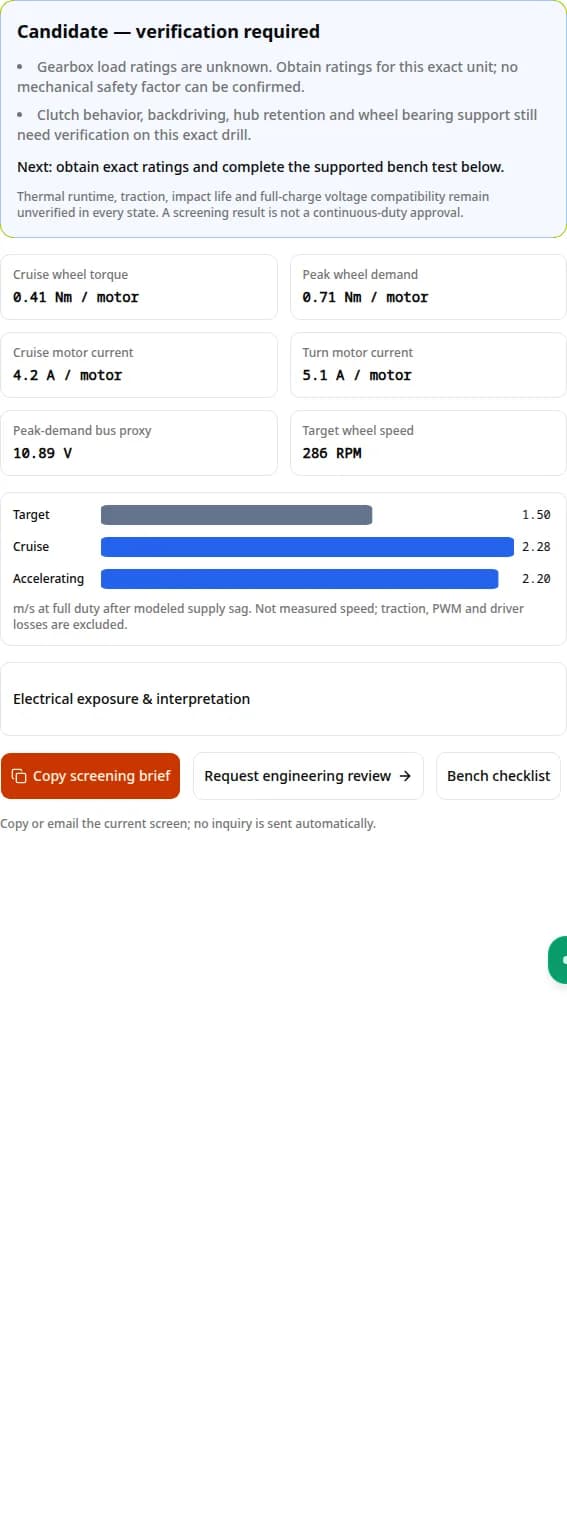
36:1 reduction, 100 mm wheels, 10% grade, 1.5 m/s target.
Modeled cruise capability: 2.28 m/s. No entered limits exceeded; obtain ratings and bench-test.
Check wheel torque, loaded speed and driver demand before converting a cordless drill for a robot.
Defaults: illustrative 12 V motor + 36:1 gearbox. Replace assumed data before selecting hardware. No submission needed.
A gear ratio that supplies wheel torque can still miss target speed. The tool checks both after voltage sag. [S1]
Do not treat theoretical stall torque as sustained output. Exact gearbox limits and thermal tests remain necessary. [S2] [S4]
Normal drive current does not cover a blocked wheel or braking energy. Verify the controller and supply together. [S3]
Missing an exact motor curve or gearbox rating? Request a manual engineering review with your load, wheel size and duty cycle.
This original first-order worksheet uses equal load sharing, one motor per driven wheel, a constant gearbox efficiency and a linear brushed-motor load line. The underlying motor relationships are described by maxon. It is a candidate screen, not a measured drill curve. [S1]
θ = atan(grade / 100); r = wheel diameter / 2
F_cruise = m·g·(Crr·cos θ + sin θ)
T_accel = (F_cruise + m·a)·r / motor count
T_turn = m·g·(Crr·turn multiplier·cos θ + sin θ)·r / motor count
Kt ≈ Tstall / (Istall − I₀); R ≈ Vref / Istall
I = I₀ + Twheel / (ratio·η·Kt)
Vbus ≈ Vpack − motor count·I·Rseries
n_motor ≈ n₀,ref·max(0, Vbus − I·R) / (Vref − I₀·R)
v = n_motor·π·wheel diameter / (60·ratio)
| Dimension | What is included | What remains unknown |
|---|---|---|
| Linear acceleration | Entered 0–3 m/s² plus grade and rolling force | Wheel/rotor inertia, impacts and traction limits |
| Turning | Editable rolling-resistance multiplier | Actual scrub geometry and transient tire loads |
| Motor curve | Reference-voltage speed, torque and current | Hot winding resistance, brush drop and saturation |
| Battery sag | Full-duty demand and entered series resistance | PWM, BMS limits, state-of-charge dynamics and inrush |
| Gearbox | Entered efficiency; optional verified load ratings | Tooth geometry, shock life and radial bearing capacity |
| Thermal behavior | I²R exposure only | Winding temperature, cooling and safe runtime |
Do not run an uncontrolled stall test to fill missing fields. Use the exact supplier curve or a qualified, current-limited characterization. No-load data alone cannot establish stall torque.
| Input | How to establish it | If unavailable |
|---|---|---|
| Motor identity and winding | Part number, reference voltage and matching curve | Keep the result illustrative; request a motor datasheet |
| No-load speed / current | Supported low-load test at recorded terminal voltage | Use an explicitly assumed range and compare sensitivity |
| Stall torque / current | Exact curve or qualified characterization | Do not infer from can diameter or advertised drill torque |
| Gear ratio / efficiency | Service drawing, measured ratio and supplier loss data | Record estimates; compare plausible efficiency bounds |
| Rolling / turning resistance | Pull-force and current tests on intended floor | Vary the coefficient and multiplier; do not claim floor universality |
| Pack and wiring resistance | Controlled load step: ΔV / ΔI at operating charge | Measure at the driver; do not infer from chemistry alone |
| Gear continuous / peak torque | Supplier rating with duty and shock conditions | Leave blank; mechanical capacity remains unverified |
A drill gearbox is a candidate component, not a standardized wheel-drive assembly. Designs differ: powered reverse, output backdriving and a chuck spindle lock are distinct behaviors. Review the exact service information before modifying anything.
| Check | Decision evidence | Practical alternative |
|---|---|---|
| Clutch / drill mode | Verify repeatable drive torque in the selected mode | Use a rigid rated gearmotor if it slips or cannot be qualified |
| Backdriving and braking | Confirm permitted load paths and supported brake test | Choose a transmission approved for the required behavior |
| Chuck / spindle | Identify screw retention, thread and shoulder geometry | Obtain a matched adapter drawing or replace the output assembly |
| Wheel overhang | Verify radial and bending-load ratings | Support the axle with external bearings |
| Hub retention | Prove torque retention in both directions | Use a designed positive-drive coupling |
| Enclosure and cooling | Validate airflow, guarding and contamination exposure | Request a rated enclosed assembly with duty evidence |
There is no universal pinning, adhesive, spindle-lock removal or chuck-impact procedure here. If service information and validation cannot support a modification, choose a purpose-built drivetrain.
Braking returns energy toward the supply; verify its absorption or dissipation path.
Select by continuous current per channel and peak duration under the documented cooling conditions. The Sabertooth 2x32 manual lists 32 A continuous and 64 A peak per motor; these are product-specific examples. Confirm your own driver’s current limiting and braking behavior. [S3]
| Risk | What to verify | Mitigation / next action |
|---|---|---|
| Sustained turns | Worst motor current and driver cooling | Use measured turn duty to size continuous capacity |
| Startup / blocked wheel | Peak duration and active current-limit response | Set and validate a controller limit; coordinate fuse and wiring |
| Voltage envelope | Full-charge and braking bus voltage | Keep all components within their documented limits |
| Regeneration | Battery/BMS charge acceptance and driver energy path | Follow the manual for a clamp, resistor or compatible supply |
| Cable heating / drop | Round-trip resistance, routing and temperature | Size wire and connectors for actual current and installation |
| Logic resets / noise | Bus and logic-rail measurements during maneuvers | Review grounding, suppression and regulated logic supply |
At a hypothetical 40 A pack demand, 18 mΩ total series resistance gives 0.72 V sag; 45 mΩ gives 1.80 V. These are Ohm’s-law scenarios, not measured chemistry benchmarks. Capacity, temperature, charge level and connectors all change the result.
| Supply | Main decision | Data required |
|---|---|---|
| 3S lithium polymer | Full-charge voltage and load capability | Cell specification, pack condition and measured sag |
| 4S lithium iron phosphate | Voltage compatibility across charge range | Motor/controller limits and BMS charge acceptance |
| 12 V lead-acid | Weight versus voltage under load | Capacity-specific discharge curve and connection resistance |
| Protected lithium-ion | BMS discharge and braking response | Per-cell voltage envelope and charge/discharge limits |
| Bench power supply | Whether returned energy can be accepted | Driver-approved clamp/dissipation arrangement |
A universal capacitor or TVS value cannot qualify braking safety. Use the exact controller’s energy-management method; the Sabertooth manual describes voltage-clamp outputs for power-supply operation. [S3]
No supported runtime in minutes can be derived without thermal data. Pololu’s manufacturer guidance suggests limiting continuous current to at most 25% of stall current for its brushed gearmotors; use this only as context, not as a substitute rating for a drill. [S2]
Acceptance evidence: actual loaded speed, turning current, stable temperature for the required duty, retained hubs and bearings, and verified braking bus behavior. Unknown limits require supplier review, not a green thermal badge.
| Dimension | Drill conversion | Purpose-built assembly |
|---|---|---|
| Initial acquisition | May reuse an available tool; price depends on source | Quoted price for selected motor, reduction and options |
| Integration cost | Teardown, hub, mounting, guarding and testing labor | Drawing review, adapter and commissioning labor |
| Mechanical evidence | Often incomplete for wheel loads and duty | Request load, bearing, shock and duty documentation |
| Feedback | Encoder fit and alignment may require fabrication | Check encoder resolution, interface and actual availability |
| Maintenance | Donor-model changes can affect interchangeability | Confirm spare parts, lead time and revision control |
| Material and lifetime | Inspect exact stages; do not assume a shear threshold | Verify exact bill of materials; a catalog label is insufficient |
AndyMark’s PG page lists steel and plastic gear materials and warns about stall damage. Purpose-built does not automatically mean all-metal, continuous-duty or shock-proof. [S4]
Calculated examples using the default assumptions, not customer builds or bench results. All three retain unknown gearbox ratings and thermal duty. Use the buttons to inspect every input and output above.
36:1 reduction, 100 mm wheels, 10% grade, 1.5 m/s target.
Modeled cruise capability: 2.28 m/s. No entered limits exceeded; obtain ratings and bench-test.
Keep the drivetrain; raise target speed to 5 m/s. Compare the load-line speed with the target.
Modeled cruise capability: 2.28 m/s. 2 limits exceeded; revise the drive.
Increase mass, wheel size and grade. Compare supply sag and available stall capability.
Modeled cruise capability: 0.00 m/s. 5 limits exceeded; revise the drive.
Published by Planetary Gear Motor, a motor/gearbox supplier with a commercial interest in sourcing inquiries. First repository record: . Method reviewed: . A public publication timestamp is not verified. Review again within six months or when a source or model changes. Send a correction or ask for a review.
Sources checked 2026-10-31. Manufacturer guidance supports the method and product-specific cautions below. None verifies the default drill, a generic gearbox breakage torque or a predicted service life. Formulas, comparisons and scenarios are this page’s screening analysis.
Updated August 29, 2024. Torque constant, resistance and speed–torque relationships; supports the first-order method, not the example drill ratings.
Manufacturer support, June 2, 2020. Suggests at most 25% of stall current for its brushed gearmotors. Context only: not a thermal certification for a salvaged drill.
See specifications and Power Supply sections. Product-specific current ratings and regenerative voltage-clamp guidance; do not transfer its settings to another driver.
Product page checked October 31, 2026. Lists steel/plastic gears, 12 V input and a stall-damage warning. Confirm the purchased variant and its own curve.
It is a candidate when its loaded speed, wheel torque, controller current and measured duty performance meet your requirements. Enter total mass, wheel diameter and target speed above. The default motor is an illustrative example, so replace its data before making a purchase or build decision.
More reduction lowers output speed and reduces motor torque needed for a given wheel force. Less reduction may meet a higher speed target but increase current. Compare both at the same mass, slope and target speed, then check the actual gearbox load rating. There is no universal ratio for all drills.
No. A frame description does not identify the winding, reference voltage, speed, torque constant or thermal limits. Use data for the exact motor variant. Do not substitute a larger frame and assume it will run cooler at the same operating point.
The tool applies an editable multiplier to rolling resistance as a screening proxy. Real scrub depends on wheelbase, track width, tire construction, surface and weight distribution. A turn-current measurement on the intended floor is required; the proxy is not a chassis dynamics simulation.
No. Clutch and drill-mode designs vary. Check the manufacturer service information and verify torque transmission on the exact unit. This guide does not prescribe drilling the housing, adding adhesive or defeating protective mechanisms. If a repeatable rigid drive cannot be validated, select a gearmotor designed for wheel propulsion.
No. Identify whether the mechanism permits the required backdriving and braking behavior. A lock is not automatically incompatible with powered reverse rotation. With the battery disconnected, follow service instructions; use a supported, current-limited test to validate the complete transmission. Choose another gearbox if compatibility cannot be established.
Disconnect the pack and consult the exact drill service procedure. Some chucks have a left-hand retaining screw, but thread direction, screw type and spindle dimensions vary. Identify all retainers and measure the shaft before ordering a hub; do not assume every drill uses a 3/8-24 thread.
Only if the output bearing and shaft load ratings cover the wheel overhang and impact load. Torque capability alone does not establish radial load capacity. Where data are missing, use an externally supported wheel axle and a suitable coupling, or request a rated wheel-drive assembly.
No. Acceleration current is the demand for the entered linear acceleration, grade and rolling resistance. The separate locked-rotor estimate assumes full duty, no active current limit and the entered series resistance. Startup, impacts and blocked wheels require controller protection beyond the normal load estimate.
Check continuous current per channel, peak duration, cooling conditions, voltage range, current-limit behavior and braking mode. For example, the Sabertooth 2x32 manual specifies 32 A continuous and 64 A peak per motor; that is a product-specific rating, not a recommendation for every drill. [S3]
A nominal pack label is insufficient. Compare its fully charged voltage with the exact motor, driver, BMS and accessory limits. The calculator flags a test voltage above the motor reference voltage but cannot approve overvolting or establish service life. Enter measured pack voltage for sag screening.
No universal part value covers every robot. Check the energy path, bus voltage limits and whether the battery or BMS accepts returned current. Follow the controller manual for braking clamps or resistor sizing. Sabertooth 2x32 documents a product-specific voltage-clamp arrangement for power-supply operation. [S3]
No. Material and bearing construction must be checked for the exact variant. AndyMark lists steel and plastic in the PG series and warns that stalling can damage the gearboxes. Its product specifications should not be replaced with generic RS-775 assumptions. [S4]
There is no supported generic answer. Winding thermal resistance, cooling, enclosure, ambient conditions and duty cycle are missing from a simple force model. The tool reports copper-loss exposure, not minutes of safe operation. A controlled temperature and current test or a manufacturer continuous-duty rating is required. [S1, S2]
Compare delivered motor cost plus teardown, hubs, axle bearings, encoders, testing and expected replacement labor. A purpose-built assembly is attractive when traceable ratings, repeatable mounting or serviceability matter. Request drawings and duty evidence rather than assuming every catalog gearmotor is suitable.
Include loaded torque and speed, startup and turning duty, maximum pack voltage, controller current limits, wheel overhang, mounting drawing, encoder requirements, ambient temperature, quantity and test duration. Copy the screening brief above and clearly identify which motor data are measured, documented or assumed.
Use the copied brief to request actual torque–speed curves, gearbox load limits, bearing ratings and duty evidence. Include your measured turning current and wheel overhang. Record unknowns so the supplier can address them.