
Single axis, low idle
DC inputs: 1A moving and 0.01A idle per axis.
33.1 Wh/day · 15 Ah · 40 Wp
Verify the holding mechanism before relying on the 0.01A idle draw.
Calculator + engineering guide · Published · Reviewed
Estimate supply amps, daily Wh, battery Ah and solar recharge from DC load measurements. Start with an example, then replace its assumptions.
Prepared by Planetary Gear Motor using the source-linked method below. Review every six months or when driver, battery or model assumptions change.
12V-compatible ICs exist, but driver revisions differ. A DM542E is not a direct 12V choice. Check the exact manual.
Use measured DC idle draw; winding current is a different quantity. Standstill configuration affects energy and holding capability.
Voltage drop, cold charging, stow and surge behavior need separate checks. TI calls for system-level bulk-capacitor testing.
Log DC current at the 12V source with the actual driver, motor, gearing and panel load. Include the installed cable and any 12V-to-higher-voltage converter. Measure controls separately to avoid counting them twice. If axes differ, log each and combine the energy outside this identical-axis model.
| State | What to record | What it resolves |
|---|---|---|
| Tracking burst | Moving current, burst length and moves/day per axis | Motion Wh; include acceleration and settling |
| Standstill | Source current in the actual enable / idle configuration | Dominant overnight energy and holding-mode cost |
| Stow and dawn return | Total additional motion duration and peak current | Motion reserve; use a higher moving current if required |
| Controls and converters | 24h auxiliary watts, including charger standby | Continuous draw; add heater energy as a daily average |
| Minimum battery state | Source and driver voltage during loaded start | Cable drop, battery sag and driver compatibility |
A handheld average reading can miss inrush and rapid transients. Record peak demand separately and choose a supply that meets it; the calculator’s 25% current allowance is a planning choice.
The model uses electrical energy conservation. Its percentages and default duty cycle are planning inputs, not measurements or standard requirements. All computations retain precision until display and final upward sizing.
| Output | Equation / units | Boundary |
|---|---|---|
| Motion time per axis | t = (moves × seconds/move + other seconds) / 3600, h/day | Total must not exceed 24h; stow and dawn return use entered moving current |
| Daily energy | E = N × 12 × [I_move × t + I_idle × (24 − t)] + 24 × P_controls, Wh/day | Axes counted once; source-side measurement includes installed path losses |
| Supply allowance | I = 1.25 × [N × max(I_move, I_idle) + P_controls / 12], A | 25% current margin is separate from energy reserve; not a surge rating |
| Battery minimum | Ah = E × no-sun days × (1 + reserve/100) / (V_nominal × usable fraction) | LiFePO4: 12.8V/0.80; AGM: 12V/0.50; verify pack data |
| PV minimum | Wp = E × (1 + no-sun days / recovery days) × (1 + reserve/100) / (PSH × efficiency/100) | Assumes recovery days actually deliver the entered winter PSH |
| Cable drop | ΔV = 2 × one-way metres × resistance Ω/m × peak A | Copper at 20°C; excludes joints, hot-wire resistance and dynamic source sag |
Temperature, battery aging, BMS cutoff, usable charge limits and real solar weather can reduce autonomy. This model does not solve site wind torque, motor torque-speed curves, regeneration energy or cable ampacity.
| Device / source | Supply evidence | 12V decision and limits |
|---|---|---|
| TI DRV8825, Rev. F | 8.2–45V operating supply | 12V is within the IC range. Module thermal design and minimum driver voltage still govern usable operation. |
| TMC2209, Rev. 1.09 | Low-voltage chopper driver; 12V is within its documented range | Check exact module input range, RMS current, cooling and IHOLD settings. Frame size alone is insufficient. |
| DM542E, hardware V2.0 | Section 6.2: 18–50V input | Not direct 12V. Use the exact revision manual; a boost stage changes source current and standby losses. |
Supply voltage affects current rise and available torque during motion. There is no universal “100 RPM” boundary where all steppers produce identical torque at 12V, 24V and 48V. Test the chosen motor and gearing at minimum battery voltage, including emergency acceleration.
| Choice | Benefit | Cost / risk | Required next step |
|---|---|---|---|
| 12V battery + native driver | Simple distributed power path | Long runs consume voltage margin; pack voltage varies | Check driver range from depleted to fully charged battery |
| 12V battery + boost converter | Allows an appropriate higher-voltage drive | More components, conversion loss and quiescent drain | Measure converter input at peak and idle; check transients |
| Higher-voltage distribution | Can reduce distribution current at equal power | Different charger, controls and protection architecture | Evaluate separately; this calculator models only 12V input |
| Powered holding | Motor can resist load while energized | Higher Wh and heat; torque disappears on power loss | Measure idle draw; verify fail-safe mechanical response |
| Verified brake / holding drive | May permit low idle motor current | Brake cost, wear, release power and periodic inspection | Use documented holding ratings and loss-of-power tests |
Worm, planetary and slewing labels do not establish holding capacity. Gear ratio alone cannot certify self-locking. Ask for load, lubrication, vibration and wear conditions and a tested brake or holding-drive rating.
For mechanical selection, continue with the stepper motor planetary gearbox guide.
| Gauge | Resistance (Ω/m) | Round-trip drop (V) | Drop at 12V |
|---|---|---|---|
| 10 AWG | 0.0033 | 0.132 | 1.1% |
| 12 AWG | 0.0052 | 0.208 | 1.7% |
| 14 AWG | 0.0083 | 0.332 | 2.8% |
| 16 AWG | 0.0132 | 0.528 | 4.4% |
Approximate resistances use nominal AWG copper areas and resistivity of about 0.0172 Ω·mm²/m at 20°C. Use the cable manufacturer’s maximum resistance, installation temperature and local ampacity rules for final selection. Three percent is this page’s planning target, not a universal safety standard.
Compare V_source,min − ΔV with the driver’s minimum operating voltage. Add connector loss and source sag; a low percentage drop alone does not prove compatibility.
Check full-charge voltage plus measured regenerative and switching transients against operating and absolute limits. TI section 10.1 explains why capacitor sizing needs system tests. No single TVS or capacitor value guarantees protection.
These are hypothetical calculations using the same model as the tool, not field case studies or uptime claims. Each uses 240 × 1.5s tracking moves plus 60s other motion per axis, 1.2W controls, 3 no-sun days, 3 recovery days, 3 PSH, 75% delivered efficiency and 25% reserve.
DC inputs: 1A moving and 0.01A idle per axis.
33.1 Wh/day · 15 Ah · 40 Wp
Verify the holding mechanism before relying on the 0.01A idle draw.
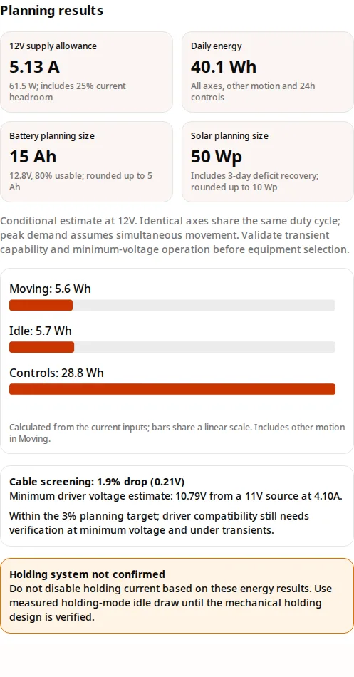
DC inputs: 2A moving and 0.01A idle per axis.
40.1 Wh/day · 15 Ah · 50 Wp
Check simultaneous-start current and minimum driver voltage.
DC inputs: 2A moving and 1A idle per axis.
607.6 Wh/day · 225 Ah · 680 Wp
Compare the larger energy budget against a verified mechanical holding option.
| Risk | Known / unknown | Mitigation or alternative |
|---|---|---|
| Wind stow or loss of power | Unknown: site load, certified holding torque and available stow torque | Have the structural/drive supplier validate the design. Do not use a generic 0° stow or wind-speed threshold. |
| Winter battery charging | Pack-specific. Victron Lithium Smart permits +5°C to +50°C charging. | Verify BMS charge inhibition and heater draw; compare a suitable alternative pack for cold sites. |
| Undersized battery or PV | Tool models energy only; weather, age and temperature remain uncertain | Log a full cycle and worst-month yield; increase reserve or recovery time using site data. |
| Surge or regeneration | Unknown: cable inductance, mechanical energy and driver clamping behavior | Measure VM during loaded starts/stops; size decoupling and protection to the exact driver. |
| Costly oversizing / wrong topology | Input accuracy and component prices are project-specific | Compare measured idle energy and full system cost before buying larger batteries. |
| Environmental mismatch | Unknown: enclosure ingress, condensation, UV and cable flex life | Specify suitable enclosures, glands, bonding and service inspection for the site. |
IEC 62817 concerns solar tracker design qualification. The catalog now lists amendment 2:2026. The public scope does not establish a universal 72-hour battery, 20 arcmin backlash or wind safety factor; confirm full applicable requirements with the project authority.
Checked October 31, 2026. Component facts below are manufacturer-specific. Calculated examples and planning allowances are labeled separately; they are not compliance claims.
Operating supply: 8.2–45V; sections 10 and 10.1 require application-specific bulk decoupling and system tests. IC ratings do not establish module continuous current.
Current regulation, standstill current and operating voltage. Thermal design and module specifications constrain usable current.
Section 6.2 specifies 18–50V input for this revision. Direct 12V operation is outside its range; check the exact hardware manual.
This product family allows charging from +5°C to +50°C. Use the chosen pack/BMS limits rather than a universal chemistry cutoff.
Public abstract establishes tracker design-qualification scope. The full standard was not used to assert numeric backlash, wind or battery requirements.
The official catalog lists amendment 2 in 2026. Confirm the applicable edition for the project; this calculator is not a compliance test.
Yes, if the exact driver supports the complete battery voltage range and the motor meets loaded torque and stow-speed requirements. The TI DRV8825 supports an 8.2–45V operating supply. This does not certify every module or motor combination. See the driver comparison and manufacturer sources below.
No. The linked Leadshine DM542E hardware V2 manual specifies 18–50V input, so 12V is below its operating range. Other revisions differ; use the exact manual. A correctly rated 24V converter or a compatible driver is required. Include converter input losses in measured 12V current.
No. A chopper driver regulates winding current; DC input current depends on bus voltage, winding resistance, motion, load and losses. Enter source-side DC measurements for moving and idle states. NEMA frame size alone cannot determine supply watts.
Ah = daily Wh × no-sun days × energy reserve factor / (battery nominal V × usable fraction). Defaults are 12.8V and 80% usable for LiFePO4, or 12V and 50% for AGM. These are planning assumptions, not manufacturer guarantees. Verify cold capacity, aging, BMS current and cutoff.
The tool supports normal daily operation while replenishing the preceding no-sun energy deficit over the selected recovery days. It also includes the entered delivered-energy efficiency and reserve. Actual weather can delay recovery; peak sun hours are not daylight hours.
No. Backdriving depends on geometry, lubrication, wear, vibration and load. Planetary and slewing drives also need model-specific holding evidence. Confirm a rated mechanical holding system and loss-of-power tests before removing motor holding current.
No universal RPM threshold applies. Current rise depends on winding inductance and resistance, driver settings, available voltage and back-EMF. Use the exact motor/driver torque-speed data and test acceleration and emergency stow at minimum battery voltage.
Defaults describe a hypothetical load, not a tested NEMA motor or finished tracker. Replace them with measured values, export the planning summary, and check supply transient capability, battery current limits and a complete loaded tracking cycle before buying.
Enter one-way source-to-driver distance. Voltage drop uses twice that distance for supply and return, approximate copper resistance at 20°C, and simultaneous peak load. It excludes connector resistance and temperature rise and does not size cable ampacity or a fuse.
No. Three percent is a planning target on this page. Compare the displayed minimum driver voltage with the exact driver operating range, including transients, source sag and hot-wire resistance. Improve cable size or shorten the run if the voltage budget fails.
Follow the exact pack and BMS charging-temperature limit. For example, the linked Victron Lithium Smart manual permits charging from +5°C to +50°C. Other packs differ. Include heater energy in the budget and confirm that charging is inhibited outside permitted conditions.
No. Wind response needs site-specific structural and aerodynamic evidence; surge protection needs driver limits, cable inductance and measured transient energy. The TI DRV8825 bulk-capacitance guidance calls for application-specific sizing and system testing. No generic capacitor or TVS value proves protection.
Send the measured load log, motor/driver part numbers, battery range, gearbox ratio, site holding loads and required stow time for engineering review. Include environmental and service requirements so the drivetrain and power system can be assessed together.