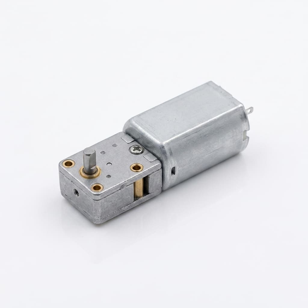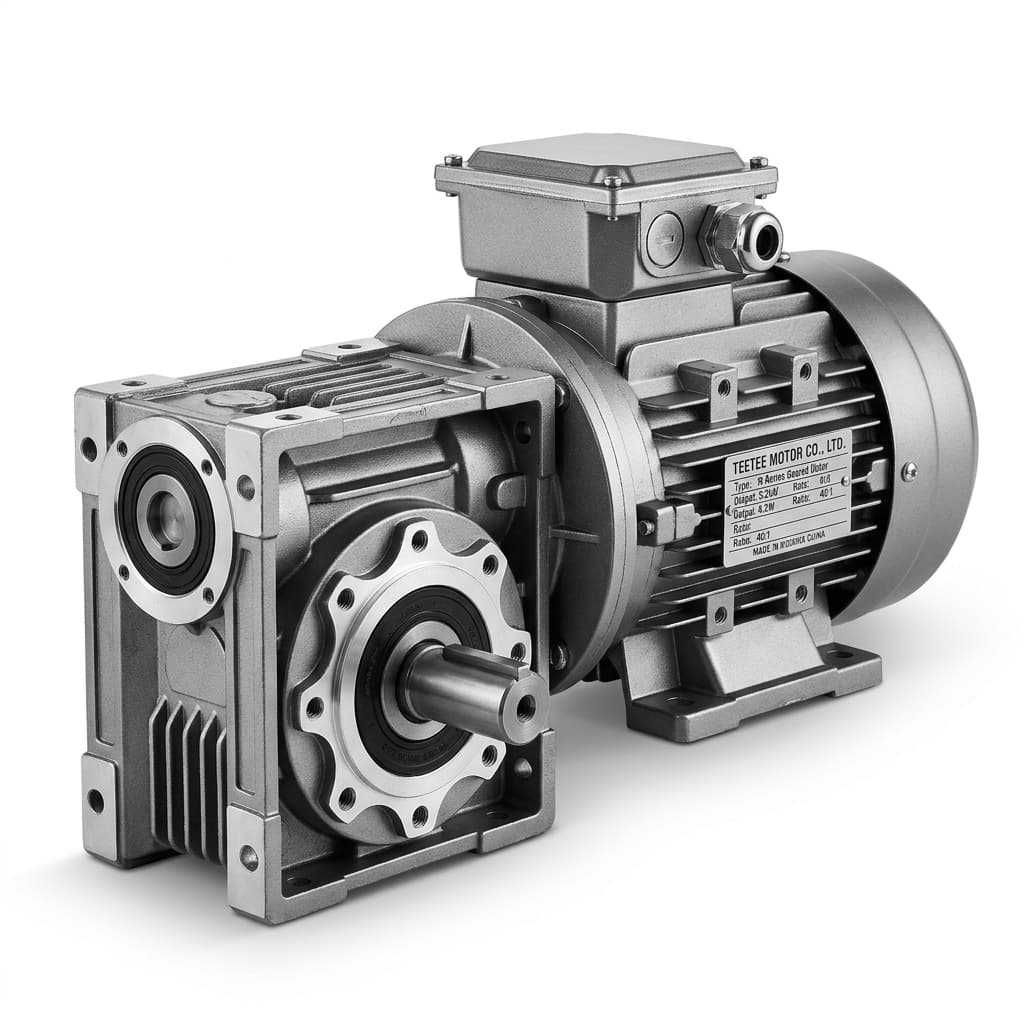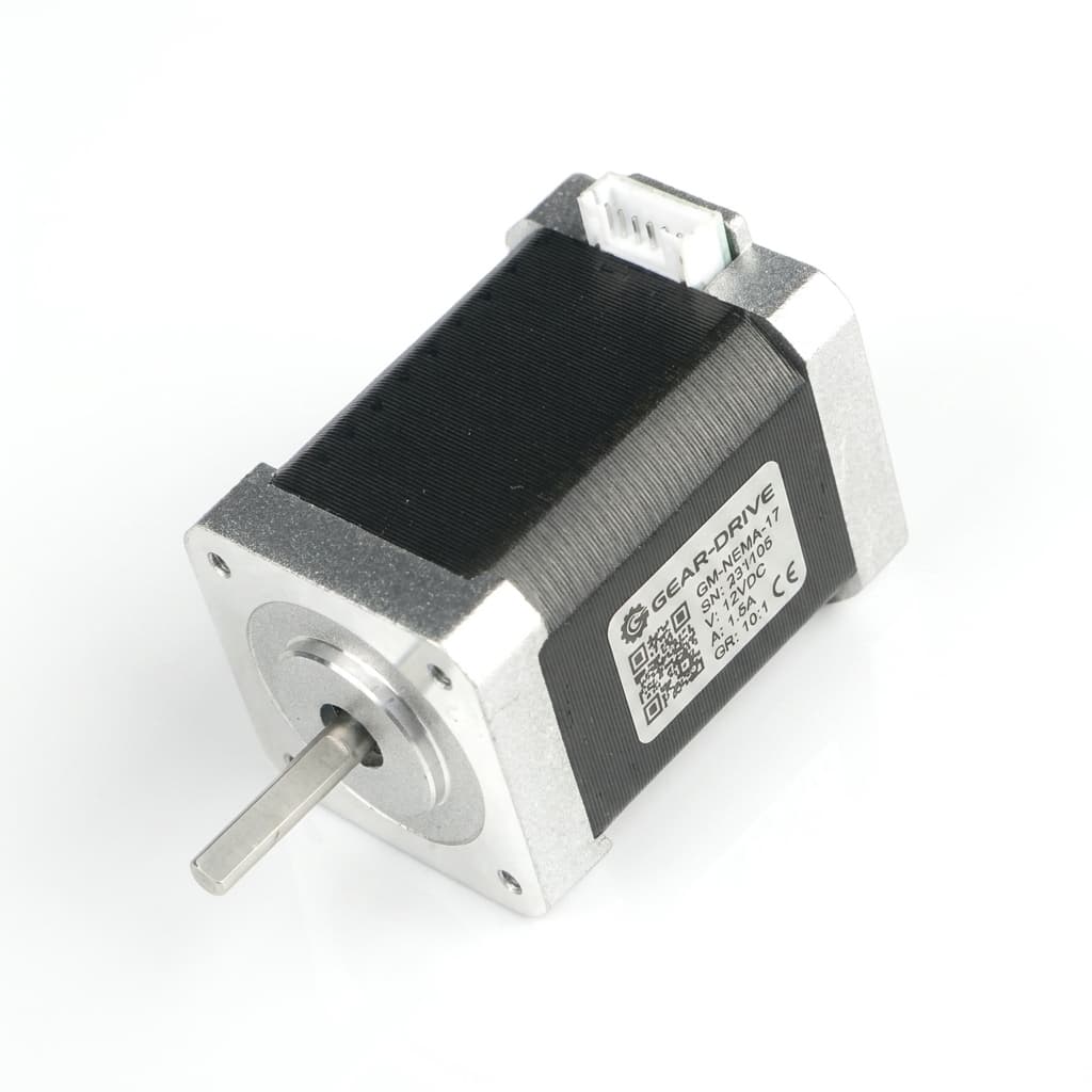
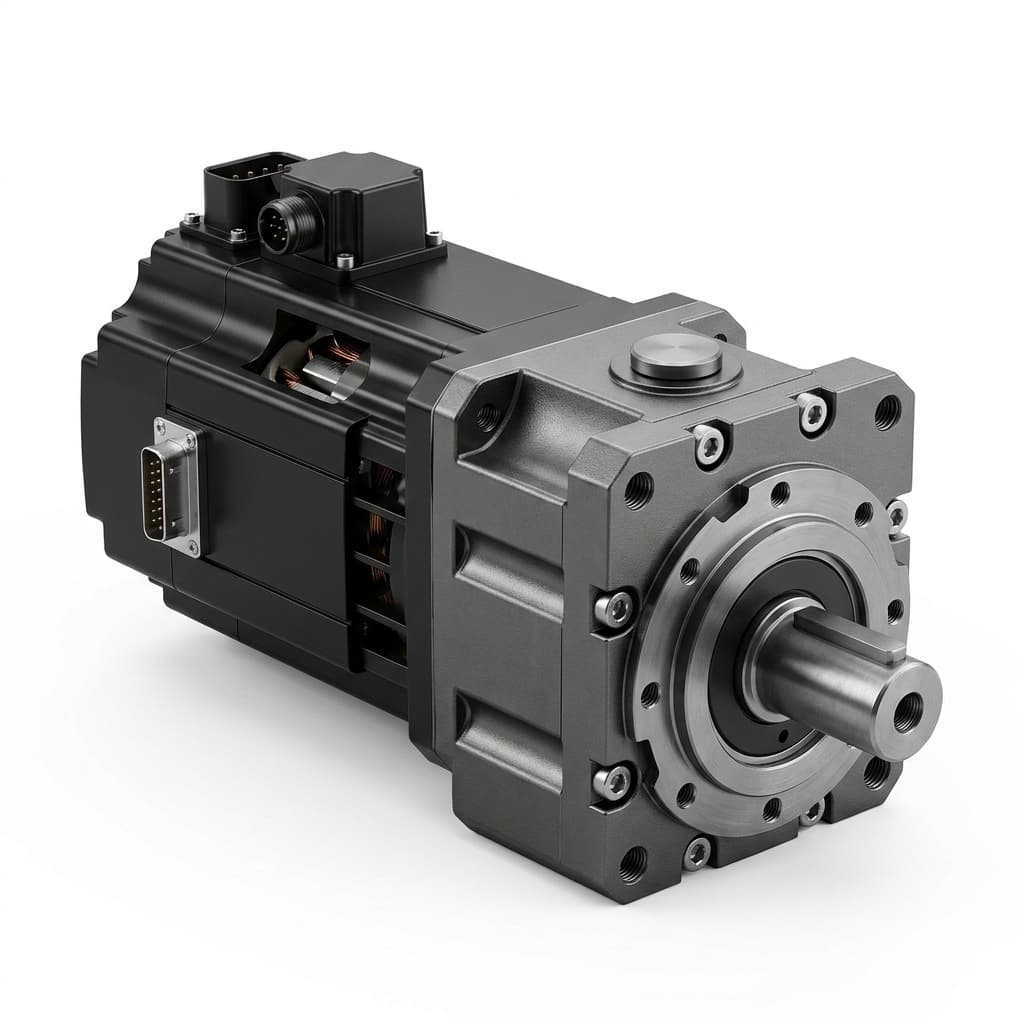
To specify overhung load (OHL) in planetary gear motors, determine the external radial force, its exact distance from the shaft shoulder, and the reaction load at each output bearing. Then check that each bearing meets the required L10h basic rating life under ISO 281. Nominal catalog torque alone does not establish radial load capacity for a pulley, pinion, or traction wheel.
When an electric motor drives a machine via a flexible coupling in pure coaxial alignment, the output shaft experiences almost pure torsion. However, the moment an engineer mounts a timing belt pulley, chain sprocket, spur gear pinion, or direct traction wheel onto the gearbox output shaft, the system enters an overhung load regime. This lateral cantilever force generates severe bending stresses across the output shaft and disproportionate reaction loads on the front output bearing.
Basic rolling bearing rating life follows a power law (L_10 ∝ (C / P)^3 for ball bearings and (C / P)^(10/3) for roller bearings). A 25% increase in equivalent bearing load reduces calculated ball-bearing life by about 49%, with all other inputs unchanged: 1 / 1.25^3 = 0.512. Shaft deflection, seal runout, lubrication, and housing stiffness require separate checks; there is no universal deflection threshold that approves every gearbox.
This guide gives OEM motion engineers and procurement teams a load calculation method, bearing architecture comparison, and OEM overhung load checklist. If your load profile is ready, request an engineering review with the mounting drawing and required service hours.
Publication and review date: October 29, 2026. Scope: English-language guidance for global OEM machinery and robotics sourcing. The worked example and service-hour budgets are hypothetical, reproducible calculations, not measured product tests or customer results. ISO 281:2007 basic rating life describes 90% survival against rolling-contact fatigue for a bearing population under its stated conditions; it is not a gearbox warranty or whole-machine reliability claim. The simple shaft model assumes two supports, a steady transverse load, and no additional gear-mesh reactions. Lubrication, contamination, internal loads, preload, shock, shaft strength, and application-specific safety requirements must be assessed separately before production approval.
1. What Is Overhung Load (OHL)? The Applied Mechanics Baseline
Overhung load (also referred to as radial shaft load, cantilever load, or external transverse force) is the total radial force (F_r) applied perpendicular to the gearbox output shaft outside the supporting housing boundary.
The Overhung Load Formula
For a transmission element with a manufacturer-specified overhung load factor, a preliminary radial-force estimate is:
F_r = (2 · T_2 / d_p) · f_z · K_a = (T_2 / R_p) · f_z · K_a
Where:
F_r: Resulting external radial overhung load [N]T_2: Transmitted output working torque [N·m]d_p: Pitch diameter of the transmission element [m] (R_p = d_p / 2is pitch radius)f_z: Transmission element factor (sometimes designatedK_r) from the applicable supplier's method [-]; it is not interchangeable across catalogsK_a: Agreed application factor [-], if that method requires it; do not apply it again when peak loads already include the same shock or acceleration
This torque-based estimate does not capture every load. A tensioned belt can exert radial force at zero transmitted torque, and vehicle weight is independent of wheel torque. Use actual force vectors and installation tension wherever available.
Transmission Loads: What Each Element Adds
Use the following force definitions instead of treating a generic multiplier as an approved load rating. Angles and force directions must match the actual installation.
| Transmission Element | Force Calculation Basis | Additional Input for the RFQ | Common Application Risk |
|---|---|---|---|
| Roller Chain Sprocket | T_2 / R_p gives tangential drive force; resolve tight-side and slack-side chain tensions at their actual angles. | Tooth count, strand tensions, chain direction, and peak acceleration. | Slack-side tension and dynamic peaks can invalidate a simple torque-only estimate. |
| Small Chain Sprocket | Use the same tension-vector method with the chain supplier's dynamic guidance. | Minimum tooth count, polygonal speed variation, and reversing duty. | Chordal action introduces cyclic loads. |
| Spur Gear / Pinion | For a 20° pressure angle, F_t = T_2 / R_p, F_s = F_t · tan(20°); shaft transverse resultant is F_t / cos(20°) ≈ 1.064 F_t. | Pressure angle, pitch diameter, load direction, and dynamic allowance. | The gear's separating force is only one component of shaft loading. |
| Helical Gear Pinion | Resolve transverse components using the transverse pressure angle; axial thrust is F_a = F_t · tan(β). | Helix angle, thrust direction, and reversal cases. | Axial thrust changes bearing load sharing. |
| Timing Belt / Toothed Belt | Sum the tight-side and slack-side tension vectors; for nearly parallel strands, shaft pull is approximately their sum. | Installed tension, strand geometry, peak torque, and belt supplier's tension method. | Static pretension remains at zero drive torque. |
| V-Belt Pulley | Use belt supplier tension calculations and strand directions. | Belt section, wrap angle, installation tension, and number of belts. | Retensioning can increase continuous bearing load. |
| Flat Belt Pulley | Resolve strand tensions using friction, wrap, and installation requirements. | Tension range, pulley geometry, and slip limits. | Increasing tension to avoid slip can overload the shaft. |
| Direct AGV / AMR Traction Wheel | Resolve vehicle weight, traction, and lateral tire forces into shaft radial/axial forces and moments. | Wheel-center offset, load distribution, floor obstacles, and steering duty. | T_2 / R_p alone omits payload weight and side scrubbing. |
2. Anatomy of Overhung Load & Bearing Reactions (Original Diagram)
When an overhung load is applied to an extended shaft, it does not act equally on the gearbox internal bearings. The gearbox output shaft is supported by an internal bearing system—conventionally two bearings spaced a distance S apart (the bearing span).
The external force F_r at distance x from the shaft shoulder creates a shoulder bending moment F_r · x. If the front bearing is a further distance b inside the housing, the bending moment at its support plane is F_r · (b + x). These are different reference planes. The two-bearing model below shows reaction magnitudes; the reactions act in opposite directions.
The following schematic details the load vector, reaction forces, bearing span, and resultant bending moment distribution:
Mechanical equilibrium model of a cantilevered overhung load on a planetary gearbox output shaft. Note how increasing distance x amplifies reaction force R_1 on the front bearing beyond the magnitude of the applied external force F_r.
3. The Distance Factor (x): Why Shaft Position Governs Bearing Longevity
A critical trap in motion component sourcing is assuming that a catalog rating of F_{r, allowable} = 3,500 N protects your machine regardless of where the pulley sits on the shaft extension.
Read the exact catalog reference plane, speed, and life basis. A supplier may rate radial load at the shaft midpoint, at a specified distance, or on a model-specific load curve. Do not assume that ISO 281 defines a universal gearbox load position.
The Static Equilibrium Mechanics
Referencing the mechanical model above, we establish static equilibrium about the inner bearing (Bearing 2):
Σ M_{Bearing 2} = 0 ⟹ R_1 · S - F_r · (S + b + x) = 0
Solving for the front bearing radial reaction force R_1:
R_1 = F_r · (1 + (b + x) / S)
And by vertical force equilibrium (Σ F_y = 0):
R_2 = R_1 - F_r = F_r · (b + x) / S
The Physical Implications
R_1is ALWAYS strictly greater thanF_r: Because(b + x) > 0, the front bearing experiences a higher radial force than the actual belt tension or gear separation force applied to the shaft.- Amplification Ratio: If the bearing span
S = 30 mm, offsetb = 10 mm, and the customer mounts a wide timing belt pulley atx = 40 mm:R_1 = F_r · (1 + (10 + 40) / 30) = F_r · (1 + 1.67) = 2.67 · F_rA1,000 Nbelt pull produces a2,667 Nfront-bearing reaction in this simplified model, before any internal gear or preload forces are added.
Distance Derating for This Two-Bearing Model
Holding the allowable front-bearing reaction constant gives the following screening relationship, derived directly from equilibrium:
F_{rx} = F_{r,ref} · (S + b + x_ref) / (S + b + x)
Here x_ref is the reference load distance and S, b, x_ref, and x use the same length unit. The ratio equals 1 at x = x_ref. For S = 32 mm, b = 10 mm, x_ref = 12 mm, and x = 32 mm, capacity at the same front-bearing reaction becomes 54 / 74 ≈ 0.730 of the reference force.
This is not a universal catalog derating formula. A separate fixed bending-moment limit at the front support would instead scale with (b + x_ref) / (b + x). Shaft strength, rear-bearing capacity, axial load, and housing deflection can govern first. Use the supplier's combined permissible-load envelope; never transplant its named constants into a different geometry model.
4. Calculating ISO 281 Rating Life (L_10h)
Under the standardized Lundberg-Palmgren fatigue theory codified in ISO 281:2007, rolling bearing fatigue life is expressed statistically. The basic rating life L_10 represents the total number of revolutions that 90% of a statistically significant population of identical bearings will complete or exceed before the first microscopic signs of subsurface fatigue flaking (spalling) appear.
The Basic Rating Life Formula
In millions of revolutions (10^6 rev):
L_10 = (C / P)^p
Converting into operational operating hours (L_10h):
L_10h = (10^6 / (60 · n_2)) · (C / P)^p
Where:
L_10h: Basic rating life in continuous operating hours [h]n_2: Bearing rotational speed [RPM], equal to output speed for the simple shaft arrangement here; use the actual ring-relative speed for other architecturesC: Basic dynamic load rating of the bearing [N] (from bearing manufacturer tables)P: Equivalent dynamic bearing load [N]p: Fatigue life exponent:p = 3.0for ball bearings (point contact)p = 10/3 ≈ 3.333for roller bearings (line contact: cylindrical, tapered, needle)
Dynamic Equivalent Bearing Load (P) for Combined Radial & Axial Loading
In a combined-load installation, first resolve radial and axial loads at each bearing, including internal gear-mesh forces and preload where applicable. For bearing i, a common catalog expression is:
P_i = X_i · R_i + Y_i · F_{a,i}
Here R_i is that bearing's radial reaction, not the external shaft load F_r. F_{a,i} is its share of axial thrust. Obtain X_i, Y_i, and any threshold e from the exact bearing manufacturer's tables and arrangement rules. Some methods include a ring-rotation factor; follow that method consistently instead of adding a universal multiplier. Paired angular-contact and tapered bearings also require the supplier's preload and induced-thrust calculation.
For the purely radial, inner-ring-rotating ball-bearing example below, P_1 = R_1. Check the rear bearing separately. Basic rating life does not replace lubrication/contamination assessment or a static check of peak loads using C_0 / P_0. For a variable-speed duty cycle, calculate damage for each loaded segment; stationary holding loads require a static check rather than substituting zero speed into the hours formula.
Numerical Engineering Example: The Cost of a 20 mm Lever Arm Error
Consider a hypothetical automated packaging axis. Inputs below are assumptions for illustrating geometry sensitivity, not a named product's specification or a belt supplier's approved tension calculation:
- Transmitted output torque:
T_2 = 120 N·m - Output rotational speed:
n_2 = 150 RPM - Timing belt pulley pitch diameter:
d_p = 80 mm = 0.08 m(pitch radiusR_p = 0.04 m) - Assumed timing belt screening factor:
f_z = 1.35; actual installed tension must still be confirmed - Assumed application factor:
K_a = 1.15, applied once - Front output bearing: Deep groove ball bearing, dynamic capacity
C = 16,800 N - Bearing span:
S = 32 mm, shoulder offsetb = 10 mm
Step 1: Calculate Applied Overhung Load (F_r)
F_r = (T_2 / R_p) · f_z · K_a = (120 / 0.04) · 1.35 · 1.15 = 3,000 · 1.5525 = 4,657.5 N
Case A: Optimal Design — Pulley Mounted Close to Shoulder (x_A = 12 mm)
R_{1,A} = F_r · (1 + (b + x_A) / S) = 4,657.5 · (1 + (10 + 12) / 32) = 4,657.5 · 1.6875 = 7,859.5 N
Equivalent load P_A = 7,859.5 N.
Calculating L_10h:
L_{10h,A} = (10^6 / (60 · 150)) · (16,800 / 7,859.5)^3 ≈ 1,085 hours
Case B: Inefficient Design — Pulley Shifted Outward (x_B = 32 mm)
R_{1,B} = F_r · (1 + (b + x_B) / S) = 4,657.5 · (1 + (10 + 32) / 32) = 4,657.5 · 2.3125 = 10,770.5 N
Equivalent load P_B = 10,770.5 N.
Calculating L_10h:
L_{10h,B} = (10^6 / (60 · 150)) · (16,800 / 10,770.5)^3 ≈ 422 hours
Engineering Takeaway
Shifting the pulley 20 mm outward increased front bearing reaction force by 37% and slashed bearing life by 61% (from 1,085 hours down to 422 hours).
If the buyer requires 30,000 hours of basic rating life, neither assumed bearing arrangement meets that target. With unchanged ball-bearing geometry and speed, the front bearing alone would require approximately C = 50.8 kN in Case A or 69.6 kN in Case B, using C_required = P · (60 · n_2 · L_10h / 10^6)^(1/p). These are screening results, not available product ratings.
Even an assumed roller bearing with C = 38,000 N and p = 10/3 gives only about 21,235 hours in Case A and 7,429 hours in Case B if the same equivalent loads are retained. Actual tapered-bearing loads must be recalculated for induced thrust and preload. Consider a shorter overhang, greater bearing span, larger suitable bearings, or a separately supported load shaft; bearing type alone cannot establish compliance. Use the OEM RFQ template to request the supplier's calculation and load envelope.
5. Output Bearing Architectures: Engineering Comparison
To handle high overhung loads without premature failure, gearbox manufacturers employ distinct bearing topologies. OEM procurement teams must evaluate these architectures when comparing suppliers and pricing tiers.
The following six configurations are selection options. Capacity, friction, and price depend on size, part number, bearing span, seals, lubrication, and preload; there is no defensible universal cost or capacity multiplier between these rows. Obtain the bearing-specific ratings from the SKF rolling-bearing catalog entry point or the selected bearing supplier.
| Bearing Architecture | Useful Design Feature | Axial / Moment Consideration | Friction and Sourcing Trade-Off | Evidence to Request |
|---|---|---|---|---|
| Dual Deep Groove Ball Bearings | Compact, readily available radial support. | Axial capability depends on the bearing and locating arrangement. | Often a simple package; a short span can amplify bearing reactions. | Part numbers, C, C_0, actual span, and combined-load limits. |
| Widely Spaced Deep Groove Ball Bearings | Greater span reduces reactions for the same overhang. | Housing and shaft stiffness still govern deflection. | Requires more axial installation space. | Section drawing, housing stiffness assumptions, and revised reactions. |
| Angular Contact Pair, Back-to-Back | Contact geometry can provide axial support and moment stiffness. | Pair orientation, preload, and thrust reversal matter. | Preload influences heat, drag, and assembly tolerance. | Pair designation, preload class, load distribution, and thermal check. |
| Paired Tapered Roller Bearings | Suitable for combined radial and axial loads when correctly sized. | Include induced axial forces and the effective pressure-center span. | Adjustment, lubrication, and preload affect losses and life. | Bearing arrangement, operating clearance/preload, and both bearings' life calculations. |
| Cylindrical Roller + Locating Bearing | Separates strong radial support from the locating function. | Axial capability depends on roller design and the locating bearing. | Additional components and fit requirements can complicate assembly. | Which bearing carries thrust, minimum-load requirements, fits, and thermal float. |
| Flanged Output / Hub Cartridge | Can put the load plane close to a dedicated support. | Verify radial, axial, and overturning-moment limits together. | Cartridge replacement and mounting requirements affect total cost. | Complete load envelope, bolt-interface limits, bearing data, and service procedure. |
6. Shaft Bending Deflection, Elastic Limits, and Seal Failure
Even if an internal bearing possesses sufficient L_10h fatigue life on paper, high overhung load can cause premature failure through a completely different physical mechanism: elastic shaft bending deflection.
The Beam Deflection Mechanics
For the idealized two-simple-support model shown above, with a uniform shaft section and overhang l = b + x, Euler-Bernoulli theory gives load-point deflection magnitude:
δ_load = F_r · l^2 · (S + l) / (3 · E · I)
The familiar fixed-cantilever formula F_r · l^3 / (3 · E · I) assumes a rigid clamp; the shaft shoulder is not automatically a clamp. Real stepped shafts require a piecewise beam or finite-element model including bearing and housing compliance. Load-point deflection also differs from deflection at the seal journal.
Where:
δ_load: Transverse elastic deflection at load point [m]; use metres forlandSin this formulaE: Modulus of elasticity of shaft steel (≈ 2.06 × 10^{11} N/m^2or206 GPafor carburized 20CrMnTi or 42CrMo4)I: Area moment of inertia of solid circular shaft:I = (π · d^4) / 64[m^4]d: Output shaft diameter [m]
Why Shaft Deflection Destroys Gearboxes
-
Radial Lip Oil Seal Leakage: The output shaft oil seal (typically NBR or FKM rubber) relies on a delicate hydrodynamic lubricating meniscus between its elastomeric sealing lip and the ground shaft journal.
- Acceptance Limit: Obtain permitted dynamic runout, static eccentricity, surface finish, speed, and temperature from the exact seal supplier. Do not apply a universal
50 µmlimit. - Failure Risk: Excess motion at the seal journal can cause leakage and contaminant ingress. The onset and time to damage depend on the seal, lubricant, environment, and operating cycle.
- Acceptance Limit: Obtain permitted dynamic runout, static eccentricity, surface finish, speed, and temperature from the exact seal supplier. Do not apply a universal
-
Internal Planet Carrier Misalignment: In an integrated output-carrier design, shaft tilt can affect planet alignment and tooth contact distribution.
- Require the gearbox supplier to check contact patterns and gear stresses under the specified external forces. Acceptable tilt depends on tooth geometry, carrier support, clearances, and housing stiffness.
-
Combined Bending and Torsion Screening: For a solid circular section, the nominal bending stress at the shoulder plane is:
σ_b = (32 · F_r · x) / (π · d^3)Combined with torsional shear stressτ = (16 · T_2) / (π · d^3), the equivalent Von Mises stress is:σ_v = \sqrt{σ_b^2 + 3 · τ^2}This nominal Von Mises combination is a static screening check, not a fatigue-life calculation. Assess alternating and mean stresses, rotating bending, material condition, surface finish, and fillet/keyway fatigue notch effects separately. The project must define its allowable stress and safety factor; check other shaft sections using their actual bending moments.
7. Setting an L10h Target from the OEM Duty Schedule
Start with a documented duty schedule, replacement interval, and reliability requirement. The table below converts illustrative assumptions into rotating-hour budgets using hours/day × days/year × years. These are not industry minimums or measured field lives. A rotating-hour budget is an input to selection, not proof that a bearing or complete machine meets the required reliability.
| OEM Application Profile | Assumed Rotating Duty | Planning Horizon | Calculated Rotating-Hour Budget | Additional Qualification Required |
|---|---|---|---|---|
| Warehouse AGV / AMR Drive | 20 h/day × 300 days/year | 5 years | 30,000 h | Wheel load distribution, floor impacts, tire side forces, and maintenance interval. |
| Packaging Infeed Belt | 16 h/day × 250 days/year | 5 years | 20,000 h | Installed belt tension and acceleration/reversal load segments. |
| Machine Tool Gantry | 8 h/day × 250 days/year | 10 years | 20,000 h | Rack force direction, thrust, stiffness, and emergency stops. |
| Solar Tracker | 1 h/day × 365 days/year | 10 years | 3,650 h | Stationary wind loads, static safety, oscillation, and corrosion. |
| Medical Positioning Axis | 3 h/day × 250 days/year | 10 years | 7,500 h | Application risk assessment and the required system reliability. |
| Access Gate | 500 cycles/day × 10 s rotating/cycle × 300 days/year | 10 years | About 4,167 h | Cycle count, stationary holding loads, and end-stop impacts. |
| Continuous Conveyor | 24 h/day × 330 days/year | 10 years | 79,200 h | Contamination, shock, lubricant life, and planned bearing replacement. |
Agree whether the RFQ target means basic L_10h, a modified life at a higher reliability, or a service/replacement interval. Multiple bearings and other failure modes make whole-gearbox survival different from one bearing's 90% fatigue-life basis. Do not turn these example budgets into universal purchasing thresholds.
8. OEM Procurement & Supplier Overhung Load Qualification Checklist
When issuing a Request for Quotation (RFQ) or approving an engineering drawing for a planetary gear motor with an overhung load, verify the following nine parameters:
- Exact Load Centerline Location (
x): Explicitly define the distancex(in mm) from the shaft mounting shoulder to the center of the gear, pulley, or wheel on the interface drawing. Prohibit generic "center of shaft" ratings without dimensional reference. - Transmission Force Declaration: State the exact element type, pitch diameter, installed tension or force vectors, and source of any screening factor. Identify which peak loads already include acceleration or shock.
- Specified Operating Life (
L_10h): Mandate the required minimum bearing life (e.g.,L_10h ≥ 30,000 hoursat specified output speedn_2and continuous working torqueT_2). Require the supplier to provide their ISO 281 calculation sheet. - Internal Bearing Architecture Callout: Confirm whether the quotation specifies standard deep groove ball bearings, angular contact bearings, or reinforced tapered roller bearings. Avoid ambiguous catalog phrases like "heavy duty bearings" without specific bearing part numbers or dynamic ratings (
C). - Allowable Axial Force (
F_a) Interaction: If your application involves helical pinions, bevel transfers, or leadscrews, require a combined radial-axial interaction envelope diagram (F_rvs.F_acurve) rather than isolated single-axis limits. - Shaft Deflection at Seal Journal: Agree maximum static eccentricity and dynamic runout with the selected seal supplier, and require a shaft/bearing/housing deflection calculation at the seal plane.
- Shaft Fillet and Keyway: Require a dimensioned interface drawing and strength/fatigue assessment of transitions and keyways; confirm the mating hub clears the fillet.
- Static Peak Overload Rating (
S_0): RequireS_0 = C_0 / P_0for each bearing under agreed emergency-stop, jam, impact, and holding cases. Agree the minimum factor for the bearing type and application rather than imposing one universal value. - Incoming Inspection Alignment (IQC): Agree drawing-based runout and no-load drag limits, measurement location, temperature, speed, instrument, sample plan, and acceptance record.
FAQ
What is the difference between dynamic overhung load and static radial capacity?
A gearbox's dynamic permissible shaft load depends on the stated speed, load position, life target, and all applicable component limits. A bearing's basic static rating C_0 uses the ISO 76 rolling-contact deformation criterion; it is not a complete gearbox shock limit or shaft yield rating. Calculate equivalent static bearing load P_0 and the required static safety factor, then check shaft and housing strength separately. There is no universal ratio between a gearbox's static and dynamic permissible shaft loads.
Can I install an outboard pillow block bearing to support an extreme overhung load?
Yes, with a designed support and alignment arrangement. Adding a bearing to an already supported gearbox shaft can create a statically indeterminate system whose loads depend on fits, stiffness, alignment, and thermal expansion. There is no universal 0.02 mm alignment tolerance. A separately supported driven shaft joined through a suitable flexible coupling can decouple the gearbox from the external radial load; have the gearbox and bearing suppliers approve the arrangement.
How does output rotational speed affect permissible radial force?
Because bearing fatigue life is measured in total accumulated revolutions (L_10 = 60 · n_2 · L_10h / 10^6), allowable radial load decreases as output rotational speed increases. A planetary gearbox running at 50 RPM can withstand significantly higher continuous radial force than the exact same gearbox operating at 500 RPM for the identical 20,000-hour lifespan. Always request the supplier's speed-derating curve (F_r vs. n_2) during axis sizing.
Why do timing belt drives have higher overhung load factors than chain drives?
Timing belts need installation tension to maintain engagement, so the tension on both strands can create substantial continuous shaft pull even at zero transmitted torque. Chain slack-side tension and dynamics also depend on the arrangement. Compare actual strand-tension vectors using each transmission supplier's method rather than assuming fixed universal belt-versus-chain multipliers.
What happens if an overhung load acts simultaneously with an axial thrust load?
Resolve the radial reaction and axial load carried by each bearing, then use its catalog factors to calculate P_i = X_i · R_i + Y_i · F_{a,i}. Load sharing, bearing contact angle, preload, and thrust direction matter. Angular-contact or tapered bearings may suit combined loads, but no universal axial-to-radial percentage determines the architecture; compare the exact supplier load envelopes and calculated life.
10. Authoritative Sources & Engineering Standards
The standard record below supports the rating-life scope. The manufacturer links are catalog entry points for obtaining model-specific data, not evidence for universal transmission factors, bearing cost multipliers, or the hypothetical example's inputs. Record the exact bearing/gearbox part, document revision, and calculation assumptions in the RFQ.
- ISO 281:2007 — Rolling bearings: Dynamic load ratings and rating life. Official standard record for basic dynamic rating life, the 90% reliability basis, modified-life scope, and exclusions such as wear, corrosion, and electrical erosion. The public abstract does not replace the full standard or bearing-specific catalog tables.
- SKF — Rolling bearings. Manufacturer catalog entry point for selecting the exact bearing and obtaining dynamic/static ratings, load factors, arrangement guidance, and lubrication requirements. This general page does not substantiate a numerical rating for an unspecified bearing.
- Neugart — Planetary gearbox manufacturer. Manufacturer entry point for product selection and application engineering. Obtain the selected model's permissible radial/axial loads, reference load position, speed, and life basis directly from its current data sheet or sizing report; this guide does not attribute a generic distance-derating formula to Neugart.
Method provenance: The reaction-force and distance-ratio equations are derived from the stated two-support equilibrium model. The numerical example is arithmetic on disclosed assumed inputs. Neither manufacturer link represents an endorsement or evidence that a listed gearbox passes this example.
11. Engineering Support: Optimize Your Drivetrain Overhung Load Capacity
Designing a high-reliability motion axis requires striking a precise balance between output shaft diameter, internal bearing architecture, housing rigidity, and unit manufacturing cost. Under-specifying output bearings risks catastrophic field failures and costly warranty recalls, while over-specifying heavy-duty bearings adds unnecessary rotating inertia, friction drag, and mechanical expense.
If you are developing automated machinery, AGV/AMR drivetrains, or high-duty industrial equipment, compare your requirements with our specialized engineering resources:
- Size your gearbox ratio and acceleration torque in our planetary gear ratio selection guide for AGVs and mobile robots.
- Balance precision positioning and torsional stiffness with our planetary gear motor backlash specification guide.
- Minimize acoustic vibration and resonance in sensitive equipment via our low-noise (NVH) planetary gear motor sourcing guide.
- Standardize your factory quality gates using our incoming and pre-shipment QC checklist for gear motor orders.
- Streamline supplier negotiations with our standard RFQ template for planetary gear motor OEM projects.
Ready to validate your output shaft and bearing specification?
Share your operating torque (T_2), speed/duty profile (n_2), transmission tension or wheel loads, element pitch diameter (d_p), mounting distance (x from shoulder), axial load, and target basic rating life (L_10h). Ask for the proposed bearing arrangement, calculation assumptions, and supplier-approved load envelope with the quotation.
Request an engineering review and OEM quotation.
Include a dimensioned mounting drawing and normal/peak load cases with your inquiry so the proposed gear motor can be assessed against the same requirements.