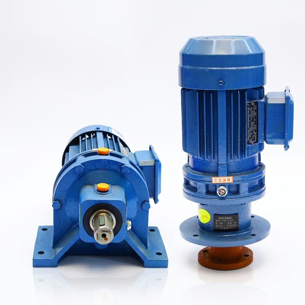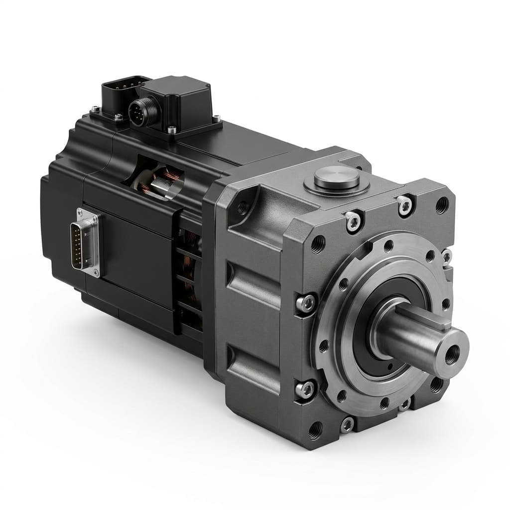
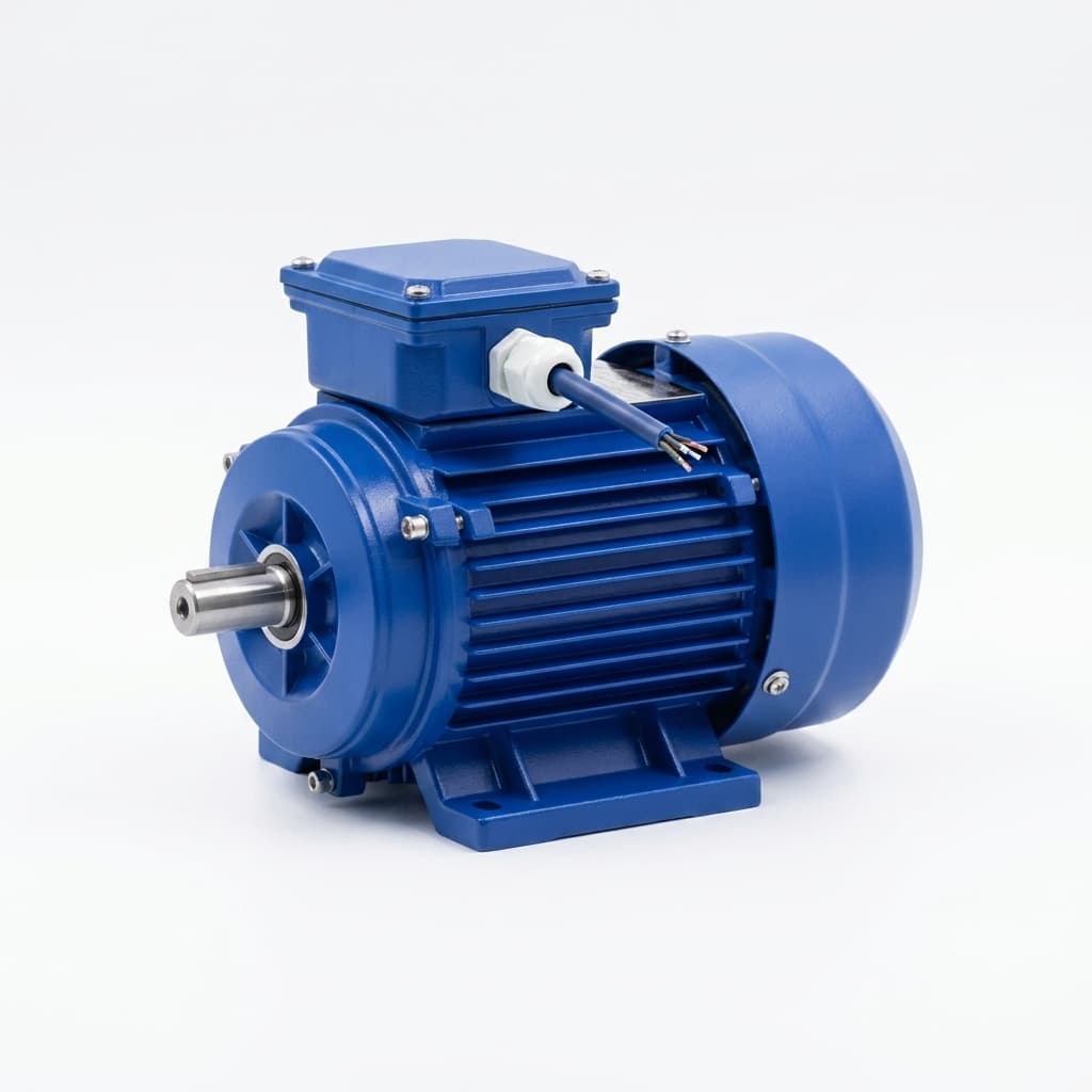
A conventional planetary gear motor should be treated as backdrivable, not as a self-locking load restraint. A high reduction ratio, resistance when turning the shaft by hand, or motor detent torque does not establish safe power-off holding on a vertical Z-axis. Specify a suitable holding device and assess the complete load path before approving a gravity-loaded drivetrain.
This guide helps OEM motion engineers and procurement teams calculate reflected torque, distinguish static holding from emergency stopping, and compare motor-side brakes with restraints closer to the load. Use the OEM vertical-axis checklist, or request an engineering review and OEM quotation with your mass, transmission geometry, speed and required safety functions.
Publication and review date: November 2, 2026. Scope: Global guidance for industrial rack-and-pinion, belt and ballscrew axes. Calculations are hypothetical, reproducible screening examples, not hardware test results or supplier ratings. Hoists, medical equipment, stage machinery and mobile robots can require additional application standards and local rules. A brake selection or torque margin alone does not establish a Performance Level (PL), a zero-drop guarantee or machine approval.
1. The Self-Locking Fallacy: Why High Ratio Does Not Establish Holding
Self-locking describes resistance to reverse motion under specified load, lubrication, temperature and vibration conditions. A planetary gearhead has no general geometric self-locking feature. Gear teeth have both rolling and sliding contact, and bearings, seals, grease and motor cogging add resistance. Whether a particular small load starts moving depends on its torque relative to that resistance.
A worm drive may resist backdriving when its lead angle is sufficiently small relative to the friction angle. This depends on the actual design and operating conditions; neither a high worm ratio nor a catalogue efficiency threshold proves safe load retention. Vibration, wear and lubrication changes can alter the result.
Why a Hand Test Is Insufficient
When turning the gearbox output, the motor runs faster by the reduction ratio. Motor inertia reflected to that output scales as J_reflected = i² × J_motor, so a high-ratio unit can feel difficult to accelerate. That observation does not establish a guaranteed holding torque over service life.
Safe Torque Off (STO) removes the drive's ability to generate torque; it does not restrain gravity or apply a mechanical brake by itself. Torque decay, remaining drag and descent acceleration depend on the drivetrain and control sequence. Assess loss of supply separately from a controlled stop.
2. Applied Backdriving Mechanics & Torque Transmission
Forward Efficiency Does Not Determine Reverse Efficiency
Forward efficiency describes motor-to-load power flow. Reverse efficiency describes load-to-motor power flow while moving. There is no universal conversion from one catalogue number to the other. At standstill, both mechanical powers are zero, so a running-efficiency equation cannot determine static breakaway torque.
| Drivetrain | What Can Resist Reverse Motion? | What the Catalogue Does Not Prove | Evidence to Request |
|---|---|---|---|
| 1-stage planetary | Mesh, bearing and seal friction | Guaranteed power-off holding | Reverse breakaway test at the specified load and temperature |
| 2-stage planetary | Additional meshes and motor resistance | Self-locking at a higher ratio | Reverse torque data for the exact motor/gearhead combination |
| 3-stage planetary | More drag and reflected motor inertia | Safe retention under sustained gravity load | Hot/cold backdrive and wear-condition limits |
| 4-stage planetary | High ratio, drag and reflected inertia | A safety-rated load restraint | Explicit holding-device specification and load-path assessment |
| Planetary + worm hybrid | Worm geometry and friction | Universal non-reversibility | Supplier reverse-motion limits, including vibration and lubrication |
| Worm reducer | Lead-angle/friction relationship | Safe lifting or personnel protection | Application approval and a separate restraint where required |
The Backdriving Torque Formula
For a moving, load-driven gearbox with fixed ring gear:
T_motor,backdrive = T_output,load × η_rev / i
Here i = n_motor / n_output is the positive reduction ratio, torque is in N·m, and η_rev is reverse efficiency under the stated operating conditions. For a rack, pinion, drum or belt pulley, T_output,load = m × g × r, with radius r in metres and g = 9.81 m/s².
For a vertical backdriven ballscrew, the load supplies mechanical input power:
T_screw,backdrive = F × lead × η_screw,rev / (2π)
Use axial force F in newtons and lead in metres per revolution. Multiplying by reverse efficiency is appropriate for load-driven motion; dividing by forward efficiency calculates the torque to raise the load. If a gearbox drives the screw, apply its reverse ratio and efficiency separately.
Conservative static screening: do not credit uncertain drivetrain friction. Use T_brake,screen ≥ S_b × T_output,load / i for a motor-side brake, or S_b × F × lead / (2π × i) for a ballscrew axis. Select the margin S_b from the application requirements and compare against guaranteed minimum brake torque after applicable derating. A minimum reverse efficiency is not conservative: higher efficiency transfers more load torque to the motor.
Why Detent Torque Is Not a Holding-Brake Rating
Unpowered cogging/detent torque varies by motor and rotor position. It differs from a stepper's energized holding-torque rating. For illustration, a 30 kg load acting on a 20 mm radius pinion creates 30 × 9.81 × 0.020 = 5.886 N·m. Even if an unpowered motor appeared to hold this load in one position, that would not establish a validated safety function.
3. Brake Latency and Unbraked Drop Distance
A spring-applied brake takes time to develop torque after its coil is de-energized. Include fault detection, control-output switching, coil field decay, armature travel and torque rise. Supplier timing definitions differ: distinguish first friction contact from a stated percentage of full braking torque.
Fault detected → brake supply switched off → field decays → torque rises → axis stops
               |<--- command-to-effective-braking delay --->|<-- stopping travel -->|
Request worst-case timing for the exact brake, controller, suppression circuit, voltage, temperature and wear state. The Mayr ROBA-servostop manual, sections 5.2.5 and 7.4–7.5 distinguishes switching modes and timing definitions. Those product-specific data cannot be transferred to every brake.
Calculating a Gravity-Only Latency Bound
For a rigid vertical axis driven only by gravity during the delay, neglecting resistance and reflected rotational inertia gives a conservative latency-distance estimate:
Δs_latency = v₀ × Δt + 0.5 × g × Δt²
Take downward velocity as positive. This is a screening bound, not a prediction that every geared axis falls at g. Rotating inertia and friction usually reduce acceleration; assisting springs, external forces or a different mechanism require a different model. For example, an ideal rack-and-pinion axis including only motor inertia has a = m × g / (m + J_motor × (i/r)²).
For a stationary axis, hypothetical delays of 25 ms and 80 ms give:
0.5 × 9.81 × 0.025² = 3.07 mmof latency travel.0.5 × 9.81 × 0.080² = 31.39 mmof latency travel.
These figures exclude travel while brake torque builds and the axis decelerates. Total overtravel must also include initial downward speed, brake dynamics, mechanical compliance, backlash and tolerances. If clearance is critical, validate the complete stopping response under controlled commissioning conditions.
Selecting the Coil Switching Circuit
DC-side interruption with suitable suppression can shorten field decay compared with a freewheel-diode or AC-side arrangement. Follow the brake and controller manufacturers' approved wiring and clamp-voltage limits. Suppression placement and rating must match the circuit; a generic MOV/TVS instruction cannot guarantee a response time or preserve the safety function. Keep motor torque established during normal brake engagement until holding is confirmed by the approved sequence.
4. Mechanical Schematics: Vertical Axis Planetary Drivetrain with Integrated Brake
This conceptual schematic shows the gravity-load path through a rack-and-pinion axis to a motor-side brake. It is not a construction drawing or a verified stopping-system design:
5. Brake Architecture: Motor-Side, Output-Side and Independent Restraint
Motor-Side High-Speed Brake
Mounting the brake on the motor shaft reduces the required torque approximately by the gear ratio, ignoring friction. For example, 3 N·m at a 25:1 ratio corresponds to 75 N·m at the output before any margin or derating. The complete mechanical chain must remain intact: a failed coupling, shaft or gear can separate the locked brake from the load.
Output-Side Low-Speed Brake
An output-side brake can bypass some gearbox failure modes, but it still depends on the shaft, hub, pinion, rack and structural attachments between its friction surface and the payload. Its required torque is the load-side torque without gear reduction. Size, weight and price require actual supplier data.
Independent Load Restraint
A separately mounted rail brake, rod lock or arresting device can provide another holding path. Check its mounting, energy capacity and independence from common failures. Two electrical coils on one brake do not automatically create two independent mechanical restraints or establish Category 4 / PL e.
The DGUV FBHM-005 guidance discusses gravity-loaded axes and measures selected for different access conditions. It is German machinery guidance, not a universal approval for hoists or medical equipment.
6. Holding Brake Technologies Compared
Each row describes a selection question, not a guaranteed rating. Obtain the exact product's minimum torque, response time, permitted speed, work per stop and service-life limits.
| Technology | Power-Off Behavior | Static Holding Use | Dynamic Stopping Boundary | Main OEM Evidence Required |
|---|---|---|---|---|
| Spring-applied electromagnetic brake | Springs engage when release power is removed | Common motor-side option | Holding-only and dynamic-rated versions differ | Minimum torque, approved controller and emergency-stop envelope |
| Permanent-magnet power-off brake | Magnetic force engages the brake without release power | Compact servo option | Friction pairing and permitted work are product-specific | Temperature limits, release conditions and permitted stopping energy |
| Sprag clutch / one-way backstop | Locks one direction mechanically | Useful where reverse operation is prohibited | Engagement speed and shock torque require checking | Direction, torque, speed and lubrication limits; unsuitable for normal bidirectional lowering |
| Rail clamp / rod lock | Depends on spring, pneumatic and hydraulic design | Can restrain nearer the load | A static clamp may not be approved to stop motion | Explicit dynamic-braking approval, holding force and rail/rod compatibility |
| Output disc caliper | Only suitable power-off designs apply automatically | Acts on the low-speed load shaft | Disc, lining and actuator must meet the duty | Static/dynamic torque, thermal envelope and actuation-loss behavior |
| Dual-brake assembly | Depends on independence of both brake paths | May support a redundant architecture | Each channel needs its own ratings and fault analysis | Separate testability, common-cause assessment and complete-system validation |
For a supplier comparison, submit the same payload, geometry and stopping duty for each quotation, and require unsupported ratings to remain explicitly unconfirmed.
7. Worked Sizing Calculation: Vertical AMR Mast Lift
This hypothetical example uses a direct rack-and-pinion mast, not a scissor linkage. A scissor mechanism needs position-dependent force analysis. No product has been tested or approved by this calculation.
| Input | Illustrative Value | Boundary |
|---|---|---|
| Suspended mass | 160 kg | Includes carriage and payload; cable forces omitted |
| Pinion pitch radius | 0.020 m | Direct vertical rack drive |
| Gear reduction | 25:1 | Motor speed divided by pinion speed |
| Moving reverse efficiency | 0.89 | Assumption for comparison; not a supplier guarantee |
| Static screening margin | 2.0 | Example design assumption; not a universal standard value |
| Command-to-braking delay | 28 ms | Assumed worst-case effective delay for the example |
| Maximum downward speed | 0.4 m/s | Initial speed before the delay |
| Motor inertia | 0.00008 kg·m² | Assumed; gearbox and brake inertia omitted |
Step 1: Calculate the Load Torque
F_g = 160 × 9.81 = 1569.6 N
T_output,load = 1569.6 × 0.020 = 31.392 N·m
Step 2: Distinguish Moving Backdrive Torque from Static Screening
With the assumed running reverse efficiency, T_motor,backdrive = 31.392 × 0.89 / 25 = 1.118 N·m.
Without crediting friction, T_motor,screen = 31.392 / 25 = 1.25568 N·m. Use this larger value for the illustrative static screen. A reverse efficiency inferred from forward catalogue efficiency would not justify reducing it.
Step 3: Apply the Selected Margin to Minimum Available Torque
T_brake,min ≥ 2.0 × 1.25568 = 2.51136 N·m
A 2.5 N·m minimum misses this example's criterion; a 3.0 N·m guaranteed minimum under the specified conditions would pass the static screen. A nominal 3.0 N·m catalogue rating still needs tolerance, temperature, wear and contamination review. Neither result demonstrates a category or PL, and dynamic stopping remains unverified.
Step 4: Screen Travel During the Delay
For a stationary axis, the gravity-only bound is 0.5 × 9.81 × 0.028² = 3.85 mm.
For an axis already descending at 0.4 m/s, it becomes 0.4 × 0.028 + 0.5 × 9.81 × 0.028² = 15.05 mm, before braking travel. A fixed 10–15 mm overtravel allowance therefore cannot be approved from the stationary calculation. Establish clearance from the complete worst-case response.
Step 5: Leave Emergency-Stop Approval Open Until Dynamic Data Exist
At the initial speed, ω_motor = (0.4 / 0.020) × 25 = 500 rad/s, approximately 4775 rpm.
Initial kinetic energy is 0.5 × 160 × 0.4² + 0.5 × 0.00008 × 500² = 12.8 + 10.0 = 22.8 J, excluding other rotating parts. This is not the required energy rating: gravity adds energy during the delay and while braking.
At brake engagement, calculate E_brake = E_kinetic,engagement + m × g × s_stop − E_other_losses using a consistent dynamic model. For conservative screening, do not credit uncertain losses. Stopping distance s_stop depends on minimum dynamic brake torque, load torque, inertia, torque rise and speed. Confirm maximum engagement speed, single-stop friction work, repeat-stop duty and lifetime work separately. A static torque rating cannot establish a 150 J or 300 J energy capacity.
8. Functional Safety: Control, Brake Testing and Fault Response
ISO 13849-1:2023 provides a method for designing safety-related control systems. It does not assign a required PL to every vertical-axis application. Define the safety functions and required PL from the machine risk assessment and applicable product standards, then validate the implemented system.
Safe Brake Control (SBC)
SBC controls the brake release supply through a safety-related output. Electrical disconnection alone cannot prove mechanical holding torque. Use the approved drive/controller architecture, required diagnostics and sequencing; assess brake failure, wiring faults, coupling failure and shared power or mounting faults. Adding two switches is insufficient to claim PL d/e.
Safe Brake Test (SBT)
A brake test can detect loss of static holding capacity. Define the test torque, dwell, schedule, permitted movement and fault response for the actual axis. Confirm whether the drive's named brake-test function has the safety properties required by the application.
DGUV FBHM-005, Table 2, gives examples of cyclic testing in a protected position. Its section on emergency stopping explains that a passed static test does not establish dynamic stopping performance. Test planning must account for this distinction.
If a test detects movement, immediately use a validated safe reaction that restrains the load and prevents access or restart. Simply disabling motor torque on a slipping vertical axis may worsen the hazard. An encoder on the motor also cannot by itself detect every downstream mechanical separation.
9. OEM Vertical Axis & Holding Brake Specification Checklist
Use this checklist with the OEM RFQ template:
- Load envelope: declare maximum suspended mass, cable forces, external forces and every operating position.
- Transmission geometry: provide ratio, pinion/drum radius or screw lead; identify variable leverage and load-path failure points.
- Reverse-motion data: request exact-unit breakaway and running data with temperature, lubrication and wear conditions. Do not size from a guaranteed minimum reverse efficiency.
- Static torque: agree on an application-specific margin and minimum available brake torque, including tolerances and derating.
- Dynamic duty: provide descent speed, inertias, stop frequency and lifetime emergency events; obtain permitted dynamic torque, speed and friction work.
- Timing and clearance: specify worst-case total delay, torque rise and allowed total travel, including power-loss stops.
- Coil and controller: match supply tolerance, duty, suppression and wiring to approved supplier instructions; include battery-voltage extremes where relevant.
- Safety architecture: record required functions, PLr, independent restraint needs, diagnostics, test coverage and documented fault response.
- Environment and maintenance: confirm temperature, moisture, corrosion, contamination barriers, inspection intervals and replacement criteria.
- Manual release and acceptance: require a load-support procedure before release, protected commissioning tests and documented acceptance limits.
FAQ
Can I use a standard motor holding brake to stop a falling vertical load?
Only if the exact brake has an adequate emergency-stop rating for the speed, load and energy involved. A holding-only brake cannot be assumed to stop motion safely. Normal stopping should follow the approved drive/brake sequence; routine friction braking requires a suitable dynamic-duty brake. Check the manufacturer's permitted emergency-event count rather than assuming a universal lifetime limit.
Why does a high-ratio planetary gearbox feel difficult to backdrive by hand?
The ratio magnifies motor inertia as seen from the output, while seals, grease and cogging add resistance. This can prevent a small hand-applied torque from starting motion. It is not evidence of a guaranteed safety restraint under maximum load, vibration, heat or wear.
Should I use forward efficiency to size a ballscrew holding brake?
For load-driven motion, screw-shaft torque is F × lead × η_screw,rev / (2π). The raising-torque formula divides by forward efficiency and answers a different question. For conservative static screening, omit uncertain friction credit and assess the full transmission path to the brake.
How does cold storage affect brake selection?
Low temperature, condensation and icing can change friction and engagement behavior. Request the exact brake/controller temperature range and validate its response under the stated environment. Room-temperature timing and torque data do not approve a freezer application.
What does an over-excitation brake controller do?
It can apply an approved release pulse followed by a lower continuous coil supply. Pulse duration, voltage and duty must match the brake design. A controller's release-time benefit does not automatically shorten power-off engagement time; do not overdrive a standard coil without manufacturer approval.
Do all collaborative robot joints require a holding brake?
No universal joint-by-joint rule follows from backdrivability. Gravity loading, counterbalance, joint orientation, mechanical restraint and the robot safety design determine the holding measures. Hand-guiding capability alone does not establish safe behavior after loss of power.
How should a vertical-axis brake be released during a power outage?
First secure the carriage with an approved mechanical support and exclude people from the danger zone. Authorized personnel should then follow the machine manufacturer's release and recovery procedure. An ad hoc battery connection or an unsupported manual release can bypass safety functions and let the load descend.
11. Sources & Engineering Reference Boundaries
Sources checked November 2, 2026. These references support the stated safety framework and product-specific limits; they do not certify the hypothetical calculation or any offered motor package.
- ISO 13849-1:2023 — Safety-related parts of control systems. Official edition record and scope for control-system design methodology. Required safety functions and PL remain application-specific.
- DGUV FBHM-005 — Gravity-loaded axes / Vertical axes, August 2021. German guidance covering risk assessment, brake testing and protective measures; see sections 2–4 and Tables 1–3. Check its scope and dated standards references before applying it to a new machine.
- Mayr ROBA-servostop Type 8981.29_01 — Operational Instructions B.8981.EN, November 2022. Manufacturer manual hosted by Mayr Singapore; sections 5.2.5, 6.1/6.5 and 7.4/7.5 cover timing, duty, sizing and electrical switching for that product family only. Obtain the current manual for the purchased variant.
12. Engineering Support & OEM Sourcing
Use these related resources to complete the drivetrain specification:
- Planetary gear ratio selection for AGVs and mobile robots.
- Overhung load and L10h bearing life specification.
- Planetary gear motor backlash specification.
- Incoming and pre-shipment QC checklist for gear motor orders.
- RFQ template for planetary gear motor OEM projects.
Request an engineering review and OEM quotation with your payload, geometry, ratio, vertical speed, duty, voltage, environment, allowable travel and safety requirements. Ask for a proposed motor/gearhead/brake combination with documented ratings and clearly identified open checks. Final machine safety validation remains part of the machine builder's approval process.