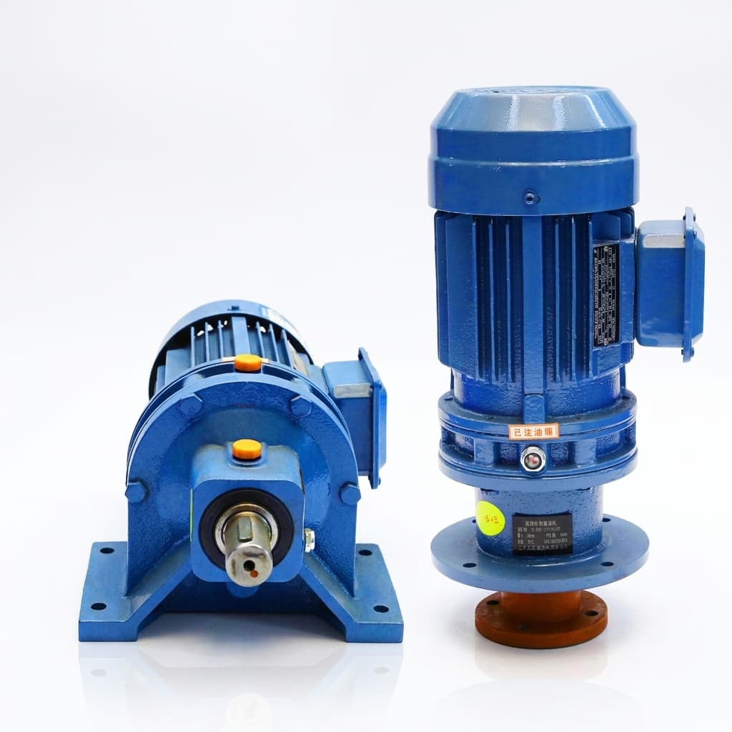
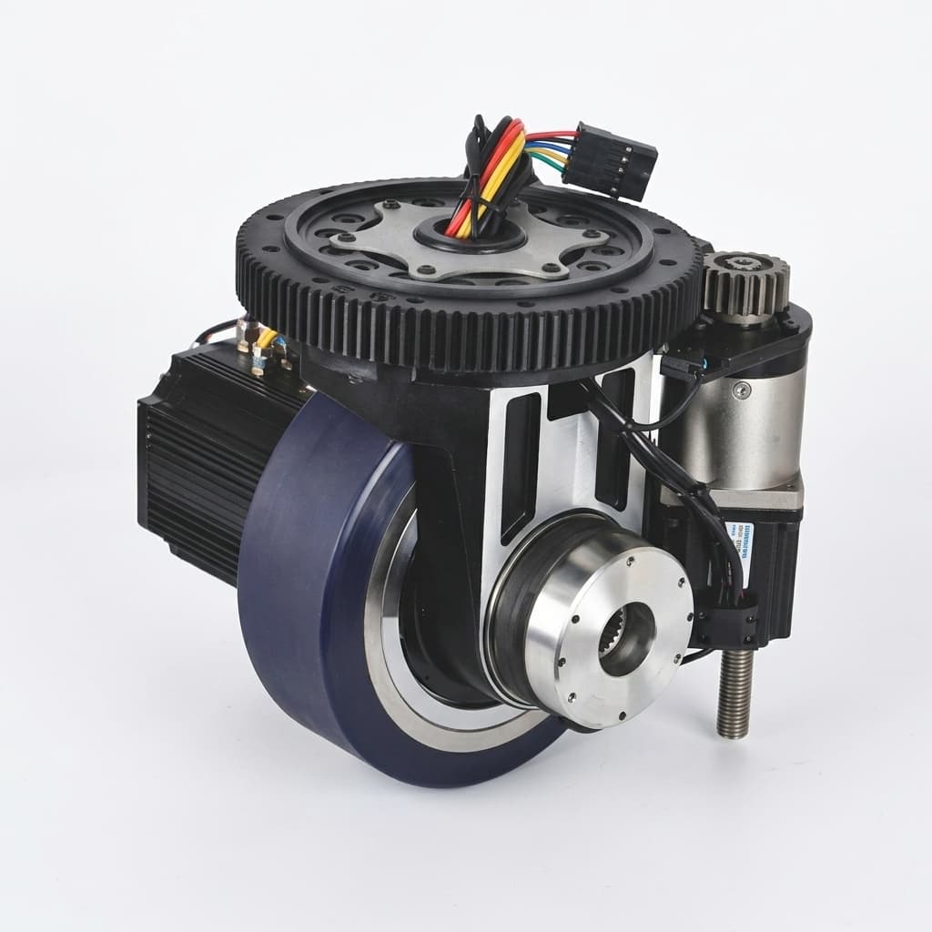
Choose a planetary gearbox for an efficient, cost-conscious general motion axis; shortlist a cycloidal/RV reducer for a stiff, heavily loaded joint; consider a harmonic (strain wave) drive when compact high reduction and low backlash dominate. Then validate the exact model against torque, speed, bearing loads and duty cycle. Architecture alone cannot establish an acceptable shock limit, positioning error or service life.
For motion engineers and OEM procurement teams, the useful comparison is a shortlist followed by a common acceptance specification:
- Planetary gear motors: Compare stage count, running efficiency and output bearing options. They are candidates for conveyors, traction and servo feeds, provided the selected unit meets the load spectrum and positioning budget.
- Cycloidal/RV reducers: Compare torsional stiffness, allowable moment and emergency-stop ratings. High-load robot joints and indexers are common applications, but input-speed and package limits remain model-specific.
- Harmonic drives: Compare high-ratio packaging, transmission accuracy and load-dependent torsional compliance. Zero geometric backlash does not mean zero positioning error or unlimited repeated overload.
This guide provides kinematic equations, a ten-metric selection matrix, a conceptual diagram, a reproducible sizing example and an OEM procurement checklist. For an application-specific shortlist, request an engineering review with your torque-speed cycle and layout.
Published and reviewed: November 6, 2026. Scope: Global B2B machinery, robotics and planetary gear motor procurement; English-language engineering comparison. Method and limitations: This is an editorial engineering analysis using the named manufacturer references below, not a comparative hardware test or a market-price survey. Catalog examples apply only to their stated series and conditions. Cost and efficiency inputs in the worked calculations are hypothetical. No operating temperature, endurance result or certification is established by these calculations.
1. Kinematic Principles: How Each Reducer Architecture Works
A speed reducer trades rotational speed for torque while introducing friction, compliance and inertia. Fix the input, output and stationary members before comparing ratios: the same gear geometry can produce different ratios when those members change.
Planetary (Epicyclic) Gearboxes
A conventional planetary set contains a central sun gear, several planet gears mounted on a carrier, and an internally toothed ring gear. For sun input, carrier output and a fixed ring:
Planetary reduction ratio:
i = n_input / n_output = 1 + Z_ring / Z_sun
Here Z is tooth count. Multiple planets provide parallel load paths, but manufacturing tolerances, bearing deflection and carrier stiffness prevent perfectly equal sharing. Do not divide tooth load by the planet count without a load-sharing allowance. Cascaded stages increase the available reduction and axial length; their losses must be evaluated for the complete gearbox rather than copied from a single-stage specification.
Cycloidal / RV Reducers
A basic cycloidal drive uses an eccentric input to move a lobed disc inside a stationary ring of pins. Output pins extract the disc's slow rotation while accommodating its eccentric motion. Opposed discs can reduce unbalanced forces, but they do not eliminate all vibration.
Basic cycloidal reduction, fixed pin ring and disc-derived output:
i = n_eccentric / n_output = -Z_lobes / (Z_pins - Z_lobes)
For one more pin than lobes: |i| = Z_lobes
Example: 60 pins and 59 lobes give 59:1, with reversed output.
The minus sign denotes opposite rotation. An integrated RV mechanism uses a preliminary spur-gear stage and a cycloidal stage; its total ratio and output arrangement must come from the RV drawing. The basic disc-output formula is not a substitute for the complete RV mechanism's kinematic equation. Distributed pin engagement can support high loads, but contact stress, eccentric bearings, main bearings and the housing still set finite limits.
Harmonic Drives (Strain Wave Gearing)
The wave generator elastically deforms a toothed flexspline inside a rigid circular spline. Teeth engage around the ellipse's major axis. With the circular spline fixed, wave-generator input and flexspline output:
Strain wave reduction ratio:
i = n_wave_generator / n_flexspline = -Z_F / (Z_C - Z_F)
If Z_C = Z_F + 2: i = -Z_F / 2
A 200-tooth flexspline and 202-tooth circular spline therefore give a 100:1 reduction with reversed output. Elastic engagement can eliminate geometric clearance, but loaded angular deflection, hysteresis, transmission error and assembly alignment remain relevant. A component set also requires an appropriate support-bearing and housing design; it cannot automatically be compared with a complete housed gearhead.
2. Reducer Architecture & Kinematic Cross-Sections (Technical Diagram)
The following conceptual schematic identifies the principal members and engagement methods. It is not a manufacturing cross-section; tooth profiles, bearing supports and dimensions are simplified.
Figure 1: Conceptual planetary, cycloidal and strain wave mechanisms. Labels identify selection checks, not measured performance or universal ratings. Scroll horizontally on narrow screens to read the diagram.
3. Engineering Comparison Matrix (10 Core Metrics)
Use this matrix to decide what evidence to request, rather than treating an architecture as a guaranteed performance class. Compare the same output torque, ratio, input speed, temperature, bearing arrangement and target life.
| Engineering metric | Precision planetary gearbox | Cycloidal / RV reducer | Harmonic / strain wave drive |
|---|---|---|---|
| 1. Ratio and stages | Low-to-moderate ratios per stage; additional stages expand the range | Basic cycloidal and integrated two-stage RV ratios differ | Compact high ratios; confirm available catalog ratios |
| 2. Backlash and lost motion | Clearance depends on precision class and preload | Specify reversal lost motion under a defined test torque | Zero backlash can coexist with elastic windup and transmission error |
| 3. Running efficiency | Request full-gearbox data at the selected ratio and load | Request speed/load/lubricant-dependent data | Request torque, speed and temperature efficiency curves |
| 4. Light-load losses | Include seal, bearing and lubricant drag | Include eccentric-bearing and lubricant drag | Include wave-generator and flexing losses; measure the operating point |
| 5. Shock overload | Compare cyclic peak and emergency limits separately | High shock capability is available, subject to model exclusions | Compare repeated-peak and momentary-peak ratings separately |
| 6. Torsional stiffness | Check the torque-deflection curve and mounting compliance | Often shortlisted for stiffness; compare actual curves | Use the applicable stiffness region rather than one constant |
| 7. Continuous input speed | Maximum speed is not necessarily an S1 continuous rating | Check complete RV input rating, not eccentric speed alone | Check average and maximum input speeds and thermal conditions |
| 8. External loads | Verify radial, axial and overturning loads at the actual offset | Integrated main bearings may carry substantial moments | Distinguish a component set from a supported gear unit |
| 9. Package and moving mass | Compare staged axial length and motor adapter | Compare main-bearing size, mass and hollow-bore needs | Compare cup/flat options and the mass of required supports |
| 10. Cost per N·m | Obtain a quote for the complete accepted configuration | Include bearings, input parts and integration | Include housing, support bearings and assembly; no universal price ratio |
Catalog evidence, not architecture-wide limits: Neugart PLFN technical data lists 96–97% efficiency and reduced-backlash options below 1 arcminute for selected sizes. Nabtesco's RV product guide describes high shock capacity, including a 5× rated-torque feature with model exclusions. Neither statement approves a particular axis without its operating conditions.
Harmonic Drive CSG-2A data illustrates why rating definitions matter: the CSG-20-100-2A-GR row lists 52 N·m rated torque, 107 N·m repeated peak and 191 N·m momentary peak. Its listed standard accuracy is 1 arcminute despite the series' zero-backlash description. Accuracy, backlash and compliance are separate specifications.
4. Deep Dive: The 5 Critical Technical Battlegrounds
Battleground 1: Geometric Backlash vs. Torsional Windup
A backlash specification alone cannot guarantee end-effector positioning. For preliminary screening, estimate clearance and elastic rotation separately:
Approximate angular error allowance = backlash allowance + T_load / C_t
Linear error at arm radius R ≈ angular error [arcmin] × π / 10800 × R
Use consistent units: T_load in N·m and C_t in N·m per arcminute. This is a simple error-budget estimate, not a manufacturer's lost-motion test definition. Torque reversal involves a hysteresis loop, and a nonlinear reducer requires its measured torque-angle curve. Encoder location, shaft coupling, structural bending and control tuning also contribute to system error.
For example, an assumed 3 arcminutes of clearance at a 0.5 m arm radius corresponds to about 0.436 mm before adding windup. If a process allows only 0.1 mm, changing the clearance class might be necessary, but the entire error budget must also close. A zero-backlash reducer with substantial loaded deflection can still miss the tolerance.
Battleground 2: Shock Loads, Emergency Stops and Failure Modes
Create separate load cases for routine acceleration, controlled braking, an emergency stop and a mechanical collision. Routine peak torque cannot be checked against an emergency-only rating. For a prescribed deceleration, a first estimate at the output is:
T_stop ≈ J_equivalent × |alpha_stop| + T_resistingAll inertia and load terms must be referred to the same shaft. Gravity and friction signs depend on direction. This equation calculates torque, not kinetic energy, and assumes a known deceleration profile. A hard collision can have a much shorter stopping time and a higher transient load than the controller's commanded stop.
For every architecture, request the allowable peak duration, repetition count and relevant fatigue calculation. Planetary teeth and bearings can fail suddenly under severe overload; cycloidal pins and eccentric bearings are not immune to damage; strain wave gears have flexspline, bearing and tooth-engagement limits. Include a torque limiter or change the stopping strategy where the supplier cannot approve the transient case.
Battleground 3: Efficiency, Battery Life and Thermal Load
Calculate losses at the actual operating points:
P_out = T_out × 2π × n_out / 60
P_in = P_out / eta
P_loss = P_out × (1 / eta - 1)
Power is in watts when torque is in N·m and speed is in rpm. These equations apply to a motoring operating point; reverse power flow requires backdriving data. At low output power, fixed drag losses can reduce efficiency in any reducer family. A full-load efficiency number cannot establish light-load battery consumption.
For a mobile machine, weight each torque-speed point by time and include motor, inverter and auxiliary losses. For thermal assessment, the same loss power can produce different temperatures depending on the mounting plate, airflow, ambient temperature and lubricant. Request a thermal rating or test with the intended installation rather than predicting a housing temperature from efficiency alone.
Battleground 4: Continuous Input Speed and Duty Cycle
Check n_input = |i| × n_output at both nominal and maximum machine speed. Separate a catalog's mechanical maximum from its allowable average or continuous speed. A short acceleration burst and a full-shift conveyor have different thermal demands even when peak rpm is identical.
There is no architecture-wide 3,000 rpm ceiling for cycloidal or strain wave drives. An RV unit's preliminary stage changes the eccentric speed relative to motor input; the complete assembly must be rated accordingly. Confirm mounting orientation, lubricant, ambient range and cooling assumptions. An intermittent cycle also needs fatigue and average-load checks: a rest period does not make its peak torque automatically acceptable.
Battleground 5: Lifecycle Economics and Cost per N·m
Use a common commercial and technical basis:
Purchase cost per rated N·m = complete quoted reducer price / accepted rated output torqueFor illustration only, assumed complete-unit bids of $300, $600 and $1,200 for equally qualified 100 N·m units normalize to $3, $6 and $12 per N·m. These are arithmetic inputs, not current market quotes or prices assigned to a reducer family. If one bid is rated only for intermittent operation, it is not an equivalent 100 N·m bid for a continuous-duty application.
Record currency, quantity, delivery terms, adapter, bearings, lubrication, inspection and warranty scope. Compare lifecycle energy, replacement labor, downtime and spare availability separately. A component set that needs custom bearings and a housing may have a different installed cost from its purchase price. Neither the cheapest purchase price nor the highest nominal torque proves the lowest lifetime cost.
If the shortlist still contains two architectures, send both suppliers the same cycle and acceptance limits through the OEM RFQ template.
5. Application Sweet Spots: Sizing Matrix by Motion Axis
When to Shortlist Precision Planetary Gear Motors
- AMR and AGV traction: Evaluate running losses, wheel overhang and reversing peaks. An integrated wheel bearing or external support may be necessary; a planetary mechanism does not itself guarantee wheel-load capacity.
- Ball-screw feeds and packaging conveyors: Compare the available ratio, continuous input speed and required backlash. Include screw inertia and coupling stiffness in the servo model.
- Continuous process equipment: Request an S1 thermal rating for the actual ambient and mounting. Food processing also needs suitable sealing, lubrication and cleaning compatibility.
When to Shortlist Cycloidal / RV Reducers
- Heavy robot base and shoulder axes: High moment and stiffness requirements make RV units candidates, but mass, acceleration and emergency-stop torque must be checked together.
- Indexers and workpiece positioners: Integrated main bearings may simplify the layout. Check the combined moment, radial and axial load envelope before removing external supports.
- Machine-tool rotary axes: Evaluate torque-angle behavior and dynamic stiffness with the machine structure. Reducer stiffness alone cannot guarantee chatter-free cutting.
When to Shortlist Harmonic / Strain Wave Drives
- Compact robot wrists and articulated joints: High reduction in a small package can reduce moving mass. Include the motor, encoder, bearings and housing in the comparison.
- Optical and medical positioning: Low backlash can help reversal accuracy, while transmission error, compliance and application-specific approval remain separate requirements.
- Limited-space rotary mechanisms: Compare cable routing, output support and backdriving torque. Do not infer a holding-brake or safety function from the reduction ratio.
6. Worked Sizing Scenario: Automated Packaging Cell Drivetrain
The following is a hypothetical preselection exercise, not a customer case study. Values are chosen to demonstrate the calculations; no reducer model, supplier quote, measured temperature or endurance test is attached to the scenario.
| Axis parameter | Case feeder belt | Reversing transfer axis | Wrist rotator |
|---|---|---|---|
| Motion demand | Continuous feed | Repeated acceleration and reversal | Fine reorientation |
| Output torque input | 65 N·m continuous | 120 N·m acceleration peak | 15 N·m while moving |
| Output speed input | 120 rpm | 180 rpm maximum | 60 rpm maximum |
| Assumed motor speed at that point | 3,600 rpm | 3,600 rpm | 3,000 rpm |
| Calculated target ratio | 30:1 | 20:1 | 50:1 |
| Clearance allowance | 8 arcmin | 3 arcmin | 0.8 arcmin |
| Applied radial force input | 1,200 N | 450 N | 60 N |
| Initial shortlist | Two-stage planetary | Compare planetary and cycloidal/RV | Compare precision planetary and strain wave |
Axis 1: Power, Motor Torque and External Load
Assume a complete gearbox efficiency of 0.92 solely for calculation. At 65 N·m and 120 rpm, output power is approximately 817 W. Required gearbox input power is 888 W, loss is 71 W, and input torque at 30:1 is 2.36 N·m. Motor and inverter losses are additional. If the assumed efficiency were 0.68 at the same output point, gearbox loss would be about 384 W. That comparison demonstrates sensitivity to efficiency; it does not assign either efficiency to every member of an architecture.
At an assumed 50 mm overhang, the 1,200 N belt force creates a 60 N·m bending moment at the chosen reference plane. Check the supplier's reference plane and combined-load limits. Neither the torque calculation nor the force alone proves that an output bearing is adequate. If the catalog supplies 32:1 rather than 30:1, 120 rpm needs 3,840 rpm input, so revisit the motor curve and continuous-speed rating.
Axis 2: Repeated Peak Is Not an Emergency Rating
A 120 N·m acceleration peak needs its duration and repetition frequency before a model can be selected. Request the complete torque-speed-time trace, cycle count, inertia and commanded stop ramp. Compare repeated-peak torque, average-load methodology, torsional deflection and settling requirements. An RV option is worth considering for stiffness, but a 20:1 target ratio may not be available in the preferred series. A precision planetary option remains valid if its measured reversal error and transient ratings meet the specification.
Axis 3: Clearance Is Only Part of the Accuracy Budget
The 50:1 target ratio gives 3,000 rpm input at 60 rpm output. A strain wave unit may fit the ratio and package, but the 0.8 arcminute clearance allowance does not specify total accuracy. Define payload inertia, loaded angular deflection, transmission error and encoder location. Fifteen N·m of working torque and a 60 N radial force do not establish moving mass, bearing life or continuous thermal suitability. Obtain the exact model's limits and a representative positioning test before freezing CAD.
7. OEM Drivetrain Reducer Selection Checklist
Use this ten-point checklist before requesting final quotations or releasing the mechanical design:
- 1. Close the positioning error budget: Specify geometric backlash, loaded reversal error, transmission accuracy and allowable end-effector displacement separately.
- 2. Check torsional windup: Use the supplier's torque-angle curve at working and acceleration loads, including coupling and frame compliance.
- 3. Define peak-load cases: Separate normal repeated peaks from emergency stops; state duration, repetition count, inertia and stopping method.
- 4. Verify thermal duty: Provide torque-speed-time data, ambient, mounting and airflow. Use the selected model's temperature limits rather than a universal housing-temperature threshold.
- 5. Request operating-point efficiency: Include cruising and startup conditions for battery systems; account for motor, inverter and auxiliary losses separately.
- 6. Verify external loads: State radial and axial forces, offsets, moments and combined-load conditions. Request bearing-life and static-load checks; ISO 281 does not establish complete gearbox life.
- 7. Confirm input speed and ratio: Check continuous, average and transient limits at the chosen ratio; identify the input and output members on the drawing.
- 8. Specify lubrication and service: Confirm lubricant, orientation, sealing, cold-start limits and maintenance access for the exact assembly.
- 9. Check integration details: Agree motor pilot, shaft clamp, flange, output bearing, brake needs, encoder location and CAD revision before ordering.
- 10. Normalize accepted quotations: Compare the same rated duty, quantity and included hardware, then record inspection criteria, warranty exclusions and spare availability.
FAQ
Does a harmonic drive's zero backlash remain zero throughout its operating life?
Zero backlash describes geometric clearance under specified conditions; it does not promise zero loaded deflection or unchanged lifetime accuracy. Wear, lubrication, installation and load history influence performance. Request the manufacturer's definition and an end-of-life reversal-error limit for the intended duty. A universal claim that backlash reaches a particular value after a fixed number of hours is not justified without test data.
Why do planetary gearboxes often need multiple stages for high ratios?
For sun input, fixed ring and carrier output, the ratio is 1 + Z_ring / Z_sun. A high single-stage ratio requires a small sun relative to the ring, constrained by tooth geometry, strength and packaging. Cascaded stages are a practical solution, not evidence of a universal 10:1 geometric ceiling. A basic cycloidal disc-output unit with one more pin than lobes instead has a reduction magnitude equal to its lobe count; an integrated RV mechanism needs its own total-ratio calculation.
Can precision planetary gearboxes achieve backlash below 1 arcminute?
Yes, selected precision products offer sub-arcminute options. The Neugart PLFN data linked above includes reduced-backlash specifications below 1 arcminute for selected sizes. Confirm size, ratio, option code and measurement conditions rather than assuming all planetary units meet that class. Also ask for torque-angle and transmission-accuracy data: tighter clearance alone does not establish total positioning performance.
How does cold ambient temperature affect harmonic versus planetary starting torque?
Cold lubricant can raise starting drag in both architectures, and the effect depends on lubricant, seals, preload and geometry. Request breakaway torque after a defined cold soak at the minimum ambient temperature. Check the motor and driver current limit with that load included. Do not assume ordinary planetary grease is suitable for outdoor cold starts or that a strain wave unit must trip its drive.
Are cycloidal reducers always heavier than planetary gearboxes of equivalent torque?
No. Compare the complete assemblies at the same ratio, rated duty, external-load capacity and life target. Cycloidal units may include substantial main bearings that a lighter component quote omits; planetary and strain wave arrangements may also require additional supports. Use installed mass and envelope dimensions from the approved drawings, including adapter, brake and housing.
What is the difference between an RV reducer and a basic cycloidal drive?
A basic cycloidal drive uses an eccentric input and a lobed disc with a pin-ring engagement. The RV arrangement described in Nabtesco's product guide combines a preliminary spur-gear reduction with a cycloidal stage and paired RV gears. This changes internal speeds and load paths. Hollow-bore availability and main-bearing capacity depend on the series; they are not automatic features of every cycloidal design.
8. Authoritative Sources and Rating Boundaries
Sources reviewed November 6, 2026. These references support the named mechanisms or catalog examples; they do not substantiate the hypothetical bids, efficiencies or axis approvals in the calculations.
- Neugart — PLFN precision planetary gearbox technical data: Model-specific ratios, efficiency, backlash options and output-load tables. Use the configured size and ratio for selection.
- Nabtesco — Precision Reduction Gear RV product guide (PDF): Operating-principle and structure/features sections describe the two-stage mechanism and qualify the shock-resistance claim. Consult the selected model's rating table; the large PDF may take time to download.
- Harmonic Drive — CSG-2A component-set specifications: Separates rated, repeated-peak and momentary-peak torque, standard accuracy and stiffness regions. Complete assembly requirements remain application-dependent.
- ISO 281:2007 — Rolling bearings: Dynamic load ratings and rating life: Bearing dynamic-rating and statistical fatigue-life framework. Basic rating life corresponds to 90% reliability under the standard's conditions; it is not a guarantee against wear or complete reducer failure. Agree the applicable edition and calculation basis with the supplier.
9. Engineering Support: Prepare a Comparable Reducer RFQ
A useful sourcing request describes the motion axis before naming a preferred architecture. Send the output torque-speed-time cycle, emergency-stop case, force offsets, ambient and mounting conditions, positioning budget, target life, quantity and delivery market. Request a model-specific rating check and identify unresolved assumptions before prototype approval.
Use these focused guides to complete the request:
- Specify cantilever forces with the overhung load and L10h bearing life guide.
- Separate clearance and rigidity with the planetary gear motor backlash specification guide.
- Review gravity and holding brakes in the backdriving and vertical-axis safety guide.
- Size a traction ratio with the AGV and mobile robot gear ratio selection guide.
- Define acceptance evidence with the incoming and pre-shipment QC checklist.
- Structure comparable supplier responses with the planetary gear motor OEM RFQ template.
Request an engineering review and OEM quotation with your motion profile and mechanical layout. Ask the team to identify candidate models, confirm the rating assumptions and provide available CAD and prototype options for your application.